Following on from previous posts about building a Raspberry Pi imaging server using Astroberry, the next stage was to add a remote focuser and dew heater control.
Remote focusers are quite expensive, however small low voltage stepper motors are both cheap, controllable and strong enough to turn a focus knob. With a Raspberry Pi attached to a telescope, GPIO control and networking is already there. Driving a motor takes little more than just a few wires, though mounting the motor and having it do something useful is a little more challenging.
For a project such as this, a 28BYJ-48 stepper motor with a ULN2003 driver module, is ideal. They usually sell for just a few pound, with many sellers offering packs of 3 for under £10. Unlike an ordinary DC motor, which spins when voltage is applied, a stepper motor will turn a set number of turns. If you track how many turns, you can turn it back to a very precise point. A more detailed explanation is available on Wikipedia.
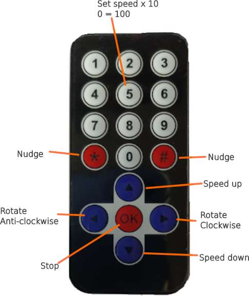
While my aim was to allow network control for focus, I also wanted something to use when doing visual astronomy and looking at bright screens is not recommended. Small IR remotes and receivers are also fairly cheap. I picked one up with 10 number buttons, ~, *, 4 directional arrows and an OK button. The advantage of using an IR focuser while at the scope, is it removes vibrations caused by hands on the telescope and can make focusing quicker.
Warning: A telescope focuser has limits and turning beyond these limits can cause damage. As a motorised focuser can not detect when these limits have been hit, going beyond them could damage your telescope. Only use a focuser for fine focus control.
Wiring
Wiring for the IR sensor, when bought on a module is fairly straight forward. Vcc and GND go to 3.3v and GND, while the data pin connects to a GPIO pin. I used pin 12, GPIO 18. The IR remote does require some setting up, see Raspberry Pi: IR Remote and Python for driving and testing.
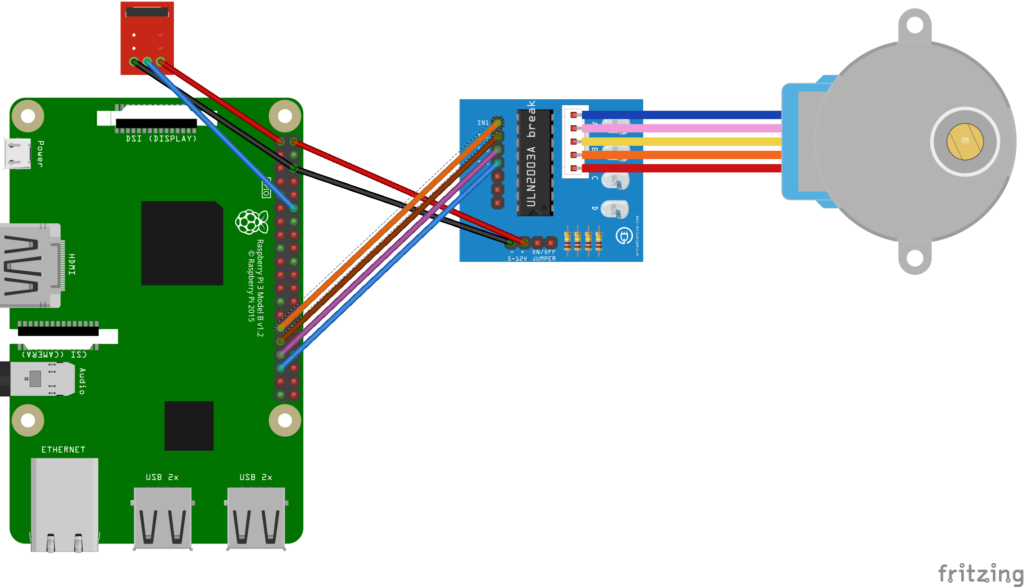
The stepper motor using a ULN2003 module requires 5V (not 3.3v) and GND to the pins on the side, then 4 of the data pins to GPIO pins. I connected as follows:
| ULN2003 | Pi Pin | GPIO Number |
|---|---|---|
| GND | 6 | GND |
| Vcc | 2 | 5V PWR |
| IN1 | 29 | GPIO 5 |
| IN2 | 31 | GPIO 6 |
| IN3 | 33 | GPIO 13 |
| IN4 | 35 | GPIO 19 |
Wanting to be able to control speed and have fine control over the motion, I was not happy with the stepper motor Python libraries I was able to find, so I produced my own, stepperLib.py in the Github repository. In the ‘hw_testing’ directory, there are stepper motor test scripts and basicFocus.py, which allows greater control of the stepper, giving keyboard driven focus control.
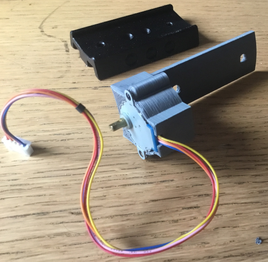
Focuser Parts
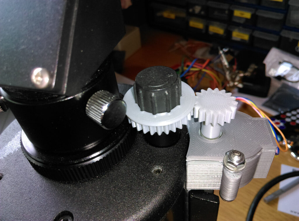
Mounting the motor securely was the most difficult part. A NexStar 90SLT is not a very big scope and ways to mount the motor are limited. My first attempt failed, then I found an article by Jason Bowling, who securely attached a stepper motor by making a bar that could fit in the gap between the scope tube and the dovetail bar. I was able to do the same using plastic rather than metal.
The two cogs were produced using a lego cog library, edited to fill in the holes. A replica of the focus knob was produced then subtracted from a cog to give a ring which slots over.
The SCAD source and printable STL files are included in the Github repository. They have also been made available online at Thingiverse.
Focuser Software
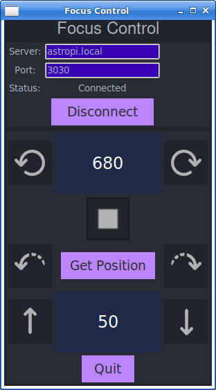
The focuser software comes in two parts, a server and a client. The server also accepts IR commands. Both written using Python, they allow the setting of speed, continuous movement clockwise and anti-clockwise, along with a single step ‘nudge’ in each direction. Note that as cogs turn in opposite directions to each other, clockwise for the focus knob is anti-clockwise for the stepper motor.
Within the software, (see Github repository), a message queue and basic command set is defined. When running, if you really want, you can telnet to the relevant port on the server IP and issue commands such as ACW for anti-clockwise motion. The focus server also makes use of the small screen I included for wifi status (see part 1), showing the focus position.
It is important to note that a stepper motor only can turn a set number of steps. It does not know what it’s starting position is at power up and will only be able to return to a known point if you count the steps. While the focus position is useful in an individual observing session, it is useless from session to session. The number displayed on the screen is just for reference for the single session to help determine where the crispest focus point is.
Probably the best way to implement this project would be to make this compatible with EKOS/INDI. However I struggled to find documentation on what the software would send to a server and what it would expect back. One popular option for DIY focusers is to make it Moonlite compatible. Initially I just wanted something up and running, working out the protocol and compatibility will come in v2 of the software.
To automatically launch the server, add it to /etc/rc.local. However while wifiStatus.py and focusServer.py can both use the display screen independently, both starting together causes a conflict. The following lines add a delay to startup to avoid this:
sleep 5 ; /usr/bin/python3 /home/astroberry/astroberryAddons/wifiStatus.py &
sleep 15 ; /usr/bin/python3 /home/astroberry/astroberryAddons/focusServer.py &
focusClient.py can be run across a network, to give a small onscreen remote.
The IR remote functions as below:
Dew heater control
During an observing session, moisture in the air can condense on a cold camera or telescope lens, blurring the view. One way to avoid this is with the use of a dew heater. There are a number of DIY and commercial options available. While a Raspberry Pi GPIO header does not have sufficient power to support a dew heater directly, you can use a relay as a switch to turn one on and off.
At the time of construction, I do not have a dew heater. However as relay boards are very cheap, it was worth adding a relay at this stage. The single relay boards (you can get 1, 2, 4 or 8 relay modules), have 3 pins. Vcc, GND and In. ‘In’ can connect to any GPIO pin. At the time of construction, I could only get a 2 channel board, bit it gives me the option of triggering two devices. I used GPIO 17 (pin 11) and GPIO 27 (pin 13). The main reason for adding these before I got a dew heater, was to make sure there was sufficient space in the case and wiring for them.
Be careful when buying relay boards for the Raspberry Pi. Some need 4v or more to trigger the input and the Pi GPIO can not deliver this. Some have a jumper to change between a high level and low level trigger, so you can select low level for the Pi. This seems to be less common on the single relay boards.
In Python, the two pins for relays must be configured as GPIO.OUT and set to HIGH to ensure the relays are off at boot. In the hw_testing directory of the GitHub repository, there are two scripts for controlling the relays. relay_test.py will alternate both relays on and off. The pins used are defined at the top of the script and can be changed. relay_off.py will ensure both relays are turned off.
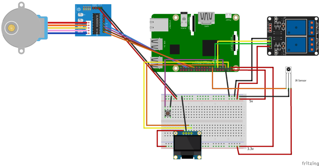
The final wiring including all hardware (using a breadboard) is:
Part 5 (link pending) details how this was assembled into a final case. Part 4 looks at controlling a Canon DSLR camera with Astroberry.
Comments