All code in this example is included in the GitHub repository.
When looking at adding a pan/tilt camera mount, I ran into a number of problems with the Raspberry Pi and serving PWM (see 9g Micro Servo performance). All series of Raspberry Pi (excluding the Pico) run PWM in software. While there are two hardware channels (pypi.org), I was going to look to these to hardware drive the main motors. This only leaves software PWM available for any servos or other hardware added later. While giving poor performance for servo motors, any software PWM is taking away CPU from any more advanced functions, especially as I look at AI in the future.
A Raspberry Pi Pico is different to a traditional Pi and does not run an operating system. You write and upload a single program, which it directly executes, very similar to an Arduino. It has 16 PWM channels and my tests found it was very good at driving even very cheap servos. Many people have used an Arduino as a slave device in robotic projects, but I have decided to use a Pico. First it is very cheap, at under £5. Secondly, the RP2040 chip it is based on has two cores. This should allow multi-threading, with one thread continually polling sensors.
As I add more sensors (especially ultrasonic distance sensors), any operations performed directly via the main Pi, will add delay while everything is polled. In theory the Pico should be able to continually poll sensors and present results to the main Pi (referred to as just ‘the Pi’ or ‘controller’ from now on) on request.
Communication between devices
There are three ways a Pi can connect to and communicate with a Pico, I2C, SPI or UART (serial). Each protocol has it’s advantages and there are many articles available on the matter. One thing all tend to agree on is that UART is easier and quick to get up and running. I have chosen to use this but may look to one of the other protocols if I get performance issues. It is not rated as the fastest or most efficient of the three protocols.
Similarly, I need to decide on a language. The Pico can be programmed in C/C++ or MicroPython. Compiled C is more efficient, however a number of tests have shown performance under MicroPython is very good. I originally decided to use MicroPython, as so far the rest of the code has been in Python (except the shell scripts and JavaScript in the web interface). There did not seem to be a need to add another language at this point. However (edit since I originally published this post), at the time of writing, multithreadding support for the Pico was considered buggy (version v1.17, published 2nd September 2021). This seems especially true when using the UART. As this is exactly what I wanted to do for the next stage, I have had to backtrack a little to investigate C++. I have used the Arduino IDE to develop the code.
All test programs are in the GitHub repository in the testing directory.
UART/Serial on the Pico
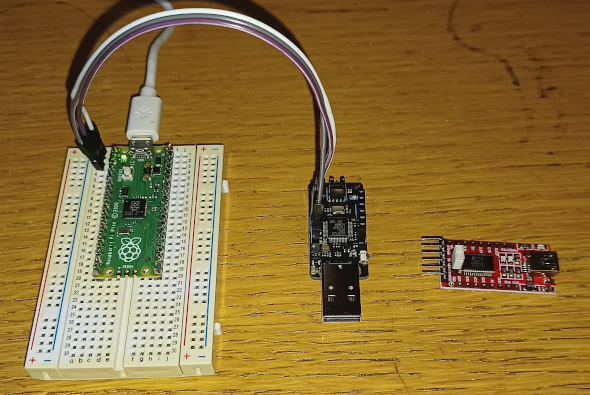
The Raspberry Pi Pico has two pins for UART channel 0, GPIO 0 (Tx, pyhsical pin 1) and GPIO 1 (Rx, pin 2). When connecting to another serial device, Tx goes to Rx on the other device and Rx to Tx. They must also share a common ground. To test communications, I needed a USB to serial adaptor. I had a Particle Debugger device that I had not used for anything, which does provide serial. However a USB FTDI adaptor such as FT232R (also pictured) will also work.
When plugging in the USB to Serial adaptor, it should register as a serial port (dmesg on Linux (/dev/tty???) or Device Manager on Windows (COM?)). There are a number of serial terminal applications that should talk to the device, screen on Linux, PuTTY on Windows or I used the Arduino IDE (both Windows and Linux). This has the advantage of being able to send complete strings.
Python
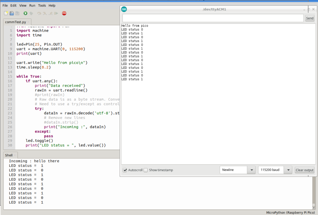
The following program will initiate the UART service on GPIO0 and GPIO1, print the current status and then go into a loop toggling the onboard LED, printing the status to the Thonny shell while also sending the status out to the serial console. Any input from the console will show in the shell as ‘Data Received’.
# Basic Pi -> Pico communication test
# This part to be run on the pico

from machine import Pin
import machine
import time

led=Pin(25, Pin.OUT)
uart = machine.UART(0, 115200)
print(uart)

uart.write("Hello from pico\n")
time.sleep(0.2)

while True:
    if uart.any():
        print("Data received")
        rawIn = uart.readline()
        #print(rawIn)
        # Raw data is as a byte stream. Convert
        # Need to use a try/except as control characters may cause an issue
        try:
            dataIn = rawIn.decode('utf-8').strip()
            # Remove new lines
            #dataIn.strip()
            print("Incoming :", dataIn)
        except:
            pass
    led.toggle()
    print("LED status = ", led.value())
    x = led.value()
    uart.write(f"LED status {x}\n")
    time.sleep(0.5)
C++
A great place to look for code guidance in C is https://github.com/raspberrypi/pico-examples. The UART code is based on the example from there.
The C version of the above code is very similar, making use of the C uart libraries. It reads the UART a character at a time with uart_getc rather than the whole buffer with uart_read_blocking. On initialisation, there is always one byte of data it appears to think it has received. Trying to read a full string caused a block, so instead I have a loop which reads one character at a time and puts this into a buffer.
Note: In the Pico SDK, the standard is to use a ‘int main()’ function where I’m using the traditional Arduino method of setup() and loop().
// Basic Pi -> Pico communication test in C++
// This part to be run on the pico
// UART reference at https://raspberrypi.github.io/pico-sdk-doxygen/group__hardware__uart.html

#include <stdio.h>
#include "pico/stdlib.h"
#include "hardware/uart.h"

// Define the UART and the standard UART pins
#define UART uart0
#define BAUD_RATE 115200
#define UART_TX_PIN 0
#define UART_RX_PIN 1

#define LED LED_BUILTIN

void setup() {
  Serial.begin(115200);
  Serial.println("Pico UART test");

  // Initialise the UART
  uart_init(UART, BAUD_RATE);
  // Convert line feeds to carriage returns to avoid
  // hello
  //      hello
  //           hello
  uart_set_translate_crlf(UART, true);
  // The first few characters are often corrupt. Send two lines to indicate start
  uart_puts(UART, "INIT\n\n");
  uart_puts(UART, "Hello from Pico\n");

  // Set the TX and RX pins by using the function select on the GPIO
  // Set datasheet for more information on function select
  gpio_set_function(UART_TX_PIN, GPIO_FUNC_UART);
  gpio_set_function(UART_RX_PIN, GPIO_FUNC_UART);

  // Init the onboard LED
  gpio_init(LED);
  gpio_set_dir(LED, GPIO_OUT);
}

bool l=0;
char msgOut[255];
char msgIn[255];

void loop() {
  // Check for input
  if(uart_is_readable(UART)) {
    Serial.println("Data received");
    uart_puts(UART, "Data received\n");
    int i=0;
    while (uart_is_readable(UART) && i<255) {
      char ch = uart_getc(UART);
      msgIn[i++]=ch;
      Serial.print('.');
    }
    Serial.print("\n");
    Serial.print("Message in:");
    Serial.print(msgIn);
    uart_puts(UART,"Message in:");
    uart_puts(UART,msgIn);
  }
  // Toggle LED value
  l=!l;
  gpio_put(LED, l);

  // Prepare outgoing message
  sprintf(msgOut, "LED status = %d\n", l);

  // To standard serial console (string has new line)
  Serial.print(msgOut);
  // Send a UART string
  uart_puts(UART, msgOut);
  delay(500);

}
It is also possible to interrupt on receiving UART data, though I have chosen not to use this at the moment.
UART/Serial on the Pi
To use UART/Serial on a Pi, the serial interface must be enabled in raspi-config as below. Note, this uses the miniUART rather than the PL011 UART. While PL011 is considered faster and more reliable, using this disables Bluetooth functions which I am going to need later.
sudo raspi-config- 3 – Interface Options
- P6 Serial Port
- ‘Would you like a login shell to be accessible over serial?’
- Answer ‘No’
- ‘Would you like the serial port hardware to be enabled?’
- Answer ‘Yes’
- Reboot
- On restart, ‘ls -l /dev/ttyS0’, should show the serial device is now present.
echo test > /dev/ttyS0- The serial console software must be set to 9600 baud to receive this text
Now the following program can be run to test serial input and output. An increasing value of x is sent to the serial port, but each time around the loop, it checks for an incoming message and will display it. The dot as it receives each chunk of incoming data shows read_until is pulling the data as one chunk. Changing this to ‘.read(1)’ will show each byte arriving. Note the baud rate changed back to 115200 from the test at 9600 above.
#!/usr/bin/python

# Com test - Pi end
# Run this bit on the Pi for basic UART/Serial communication

import serial
import time

# Init serial port and print details
sport = serial.Serial("/dev/ttyS0", 115200)
print(sport)

print("Serial test 1 - Run on the Pi not the Pico")
data="Hello from Pi\n".encode('UTF-8')
sport.write(data)

x = 0
while True:
	# Check for incoming data
	if(sport.in_waiting > 0):
		rawIn = bytearray()
		while (sport.in_waiting > 0):
			# Read until will read until we get a line ending
			rawIn += sport.read_until()
			print('.',end='')
		print("")
		print("Data Received")
		#print(rawIn)

		# Raw data is a byte stream, convert
		# Need to use a try/except as control characters may cause an issue
		try:
			dataIn = rawIn.decode('utf-8').strip()
			print("  Incoming :", dataIn)
		except:
			print("Unable to decode")

	# Output an incremental counter
	msg = "x = {}\n".format(x)
	print("Sending:",msg,end='')
	data=msg.encode('UTF-8')
	sport.write(data)
	x+=1
	time.sleep(1)
Two way communication
Now we have established both devices can communicate over GPIO pins, we can test the following workflow:
- The Pico will run with two threads:
- One thread will loop generating an array of 6 random values to simulate sensor readings
- The other thread will watch for incoming serial communications, three commands may be sent
- ‘dataRequest’ will request all sensor data to be returned as a JSON string
- ‘toggleLED’ will toggle the onboard LED
- ‘quit’ will terminate the Pico processes (reset then required)
- The Pi will sit in a loop periodically issuing ‘dataRequest’ and ‘toggleLED’ commands at different intervals.
Before starting the Pi and Pico must be connected together as follows:
| Pi GPIO | Pico |
|---|---|
| GPIO14 (Tx) – Pin 8 | GP1 (Rx) – Pin 2 |
| GPIO15 (Rx) – Pin 10 | GP0 (Tx) – Pin 1 |
| GND – Any pin | GND – Any pin |
Multithreadding the Pico
Tip: When working with multiple threads the Pico can fail to terminate or act on a stop press on Thonny, if the second thread is running. Connecting any GND pin to pin 30 (RUN) will cause a reset. Add a button between these pins as a reset button.
Having two cores, the pico can run multithreadded. A function called sensorThread will sit in a loop until the global variable checkSensors is set to False. At which point the function terminates and the thread ends. This gives us a clean way of exiting the thread.
On execution, the UART is initialised, an array (sensorData) is initialised with zero values and the sensor checking thread is started. The main loop starts where it permanently checks for incoming serial data and processes the request. It will either send the sensorData array as JSON, toggle the LED or quit. When quit is sent, the checkSensors variable is set to False. This will cause both the sensor thread and the main loop to terminate.
This will not run again until either the Pico is reset or the program is started again, e.g. Run on Thonny if running Python.
Python Code for the Pico:
# Multithredded comms test

from machine import Pin
import machine
import time
import _thread
import random
import json

numSensors = 6
sensorData = []
sensorInterval = 500      # Update simulated sensors every half second
checkSensors = True       # Flag - setting to false will terminate second thread

led=Pin(25, Pin.OUT)
uart = machine.UART(0, 115200)
print(uart)

# Sensor thread - this will simulate the sensors by filling
# the array with random values
def sensorThread():
    nextCheck=0    # When to next check the sensors
    while True:
        if(checkSensors==False):
            break
        if(time.ticks_ms()>nextCheck):
            # Update the simulated sensors
            for s in range(numSensors):
                sensorData[s]=random.randint(0,255)
            nextCheck=time.ticks_ms()+sensorInterval
    # End of 'infinite while loop
    # Thread complete, checkSensors set to false
# End of sensorThread

def sendData(str):
    # Sends data over the serial UART
    # Add new line to terminate string
    #print("Sending: ", str)
    uart.write(str+'\n')

def receiveData():
    dataIn = ""

    while uart.any():
        # In a fast enough loop, this may be called before the string
        # has completed sending. This loop will continue until the incoming
        # data has completed. On exception it will send what string it has
        # so far
        rawIn = uart.readline()
        #print(rawIn)
        # Raw data is as a byte stream. Convert
        # Need to use a try/except as control characters may cause an issue
        try:
            dataIn += str(rawIn.decode('utf-8').strip())
            #print("Incoming :", dataIn)
        except:
            pass
    return dataIn

# ******** Main code *************

# Init the sensor array with zero values
for s in range(numSensors):
    sensorData.append(0)

# Start sensor checker in new thread
_thread.start_new_thread(sensorThread, ())
# sensorThread()   # Uncomment for single thread/testing

# Main loop
while checkSensors:
    if uart.any():
        msg=receiveData()
        #print(f"Message received: \"{msg}\"")
        if(msg=="quit"):
            checkSensors=False
        elif(msg=="toggleLED"):
            led.toggle()
            sendData("ack")
        elif(msg=="dataRequest"):
            dataOut=json.dumps(sensorData)
            sendData(dataOut)
uart.write("Terminating....")
print("Completed")
C++
The C++ version is very similar in function, though as the main loop never quits, you can send a start command to restart the sensor checking thread. It does not use any form of blocking so it could cause issues if the main thread tries to change checkSensors at the same time the sensor thread is reading from it.
// Multithredded comms test
#include <stdio.h>
#include "pico/stdlib.h"
#include "pico/multicore.h"
#include "hardware/uart.h"

// Define the UART and the standard UART pins
#define UART uart0
#define BAUD_RATE 115200
#define UART_TX_PIN 0
#define UART_RX_PIN 1
#define BUFSIZE 255
#define R_TIMEOUT 1500

#define LED LED_BUILTIN
int l=0;        // Tracks LED status
#define numSensors 6
int sensorData[numSensors];
int sensorInterval = 500;
bool checkSensors=true;

void sensorThread() {
  // Sensor thread, this will simulate the sensors by filling the array with
  // random values

  int nextCheck=0;
  while(checkSensors) {
    if(millis()>nextCheck) {
      //toggleLED();        // Uncomment for activity debugging
      for(int i=0; i<numSensors; i++) {
        sensorData[i]=random(255);
      }
      nextCheck=millis()+sensorInterval;
    }
  }
}

void toggleLED() {
  gpio_put(LED, l);
  l=!l;
}

void receiveUart( char *inarr, int maxIn) {
  // Receive data from UART. Data should terminate with end of line
  // or a timeout or a full buffer
  int i=0;
  bool terminateR=false;
  int long timeout=millis()+R_TIMEOUT;
  while(!terminateR) {
    if(uart_is_readable(UART)) {
      char ch = uart_getc(UART);
      // Strip newline
      if(ch!='\n' && ch!='\r') {
        inarr[i++]=ch;
      } else {
        // Also terminate receive on new line
        terminateR=true;
      }
    }
    // Terminate receive conditions
    if(millis()>timeout) {
      terminateR=true;
    }
    if(i==maxIn) {
      terminateR;
    }
  }
  // Null terminate string
  inarr[i]=0;
}

void setup() {
  Serial.begin(115200);
  Serial.println("Pico UART test");

  // Initialise the UART
  uart_init(UART, BAUD_RATE);
  // Convert line feeds to carriage returns to avoid
  // hello
  //      hello
  //           hello
  uart_set_translate_crlf(UART, true);
  // The first few characters are often corrupt. Send two lines to indicate start
  uart_puts(UART, "INIT\n\n");
  uart_puts(UART, "Hello from Pico\n");

  // Set the TX and RX pins by using the function select on the GPIO
  // Set datasheet for more information on function select
  gpio_set_function(UART_TX_PIN, GPIO_FUNC_UART);
  gpio_set_function(UART_RX_PIN, GPIO_FUNC_UART);

  // Init the onboard LED
  gpio_init(LED);
  gpio_set_dir(LED, GPIO_OUT);

  // Turn on LED and wait 5 seconds for us to open the serial monitor
  gpio_put(LED, 1);
  delay(5000);
  Serial.println("Pico multithredding test");
  Serial.println("Starting sensorThread");
  multicore_launch_core1(sensorThread);
  Serial.println("Started");
  toggleLED();
}

char msgIn[BUFSIZE];
char msgOut[BUFSIZE];

void loop() {
  if(uart_is_readable(UART)) {
    receiveUart(msgIn, BUFSIZE);
    Serial.print("Incoming message: ");
    Serial.println(msgIn);
    if(!strcmp(msgIn, "dataRequest")) {
      // Compose JSON string manually (libraries exist for more complicated)
      strcpy(msgOut,"'[");
      char tmpStr[10];
      for(int i=0;i<numSensors;i++) {
        sprintf(tmpStr, "%d", sensorData[i]);
        strcat(msgOut,tmpStr);
        if(i!=numSensors-1) {
          strcat(msgOut, ", ");
        }
      }
      strcat(msgOut, "]'\n");
      // Send data
      Serial.print("Sending data: ");
      Serial.print(msgOut);
      uart_puts(UART,msgOut);
      // End of if dataRequest
    } else if (!strcmp(msgIn, "toggleLED")) {
      toggleLED();
    } else if (!strcmp(msgIn, "quit")) {
      checkSensors=false;
      uart_puts(UART, "Quitting thread\n");
    } else if (!strcmp(msgIn, "start")) {
      // Start the other thread
      if(checkSensors==true) {
        uart_puts(UART, "Sensor thread already running\n");
      } else {
        // Start sensor stread
        checkSensors=true;
        Serial.println("Starting sensor thread");
        multicore_reset_core1();
        multicore_launch_core1(sensorThread);
        Serial.println("Started sensor thread");
        uart_puts(UART, "Launched sensor thread\n");
      }
    }
    // Do nothing with other messages

  }
}
Creating a master program on the Pi
The master program on the Pi is very similar to the communications test program above. It will run for 30 seconds, toggling the LED every second and requesting the data every 1.5 seconds. After this it sends a quit to stop the Pico running.
#!/usr/bin/python

# Multithredded test - the Pi end
# Run this bit on the Pi for basic UART/Serial communication

import serial
import time

runTime=30			# Run for 30 seconds
toggleInt=1  		# Toggle every second
dataInt=1.5 		# Get data every 1.5 seconds

dataTimeOut=5		# Time out after 5 seconds

# Init serial port and print details
sport = serial.Serial("/dev/ttyS0", 115200)
print(sport)

print("Multithreadded test - Run on the Pi not the Pico")

def sendData(msg):
	# Send data

	print("Sending:",msg)
	data=msg.encode('UTF-8')
	sport.write(data)

def receiveData():
	# Wait for data or time out
	timeOut=time.time()+dataTimeOut
	dataIn="Error_timeout"

	while (time.time()<timeOut):
		if(sport.in_waiting>0):
			# There is data
			#print("There is data waiting")
			rawIn = bytearray()
			while (sport.in_waiting > 0):
				# Read until line ending
				rawIn += sport.read_until()
				#print('.',end='')

			# Raw data is a byte stream, convert
			# Need to use a try/except as control characters may cause an issue
			try:
				dataIn = rawIn.decode('utf-8').strip()
				#print("  Incoming :", dataIn)
			except:
				dataIn = "Error_decode"
			# We got something, drop out of loop
			#print("Data received")
			break
	# End of while loop, if a timeout then dataIn will be unchanged

	return dataIn
# End of receiveData

def send_receiveData(msg):
	# Sends data and waits for a response
	sendData(msg)
	return receiveData()


endTime=time.time()+runTime
nextToggle=0
nextData=0

while time.time()<endTime:
	if(time.time()>nextToggle):
		rtn=send_receiveData("toggleLED")
		print(rtn)
		nextToggle=time.time()+toggleInt
	if(time.time()>nextData):
		rtn=send_receiveData("dataRequest")
		print(rtn)
		nextData=time.time()+dataInt
# Loop completed, tell the Pico to stop
sendData("quit")
print("Finished")
Summary
A Pi Pico can run as a slave device to a Raspberry Pi, with two threads handling communications and actions while the other continually polls sensors which require regular updates, such as an array of ultrasonic sensors. This will give improved PWM support while freeing the Pi for other functions. However enhanced testing beyond the simplicity of the above tests have shown the MicroPython thread implementation is buggy. C++ is very stable and reliable but working with C does add complication when handling strings, dictionary structures and JSON.
The next developments are to add two servos for a pan/tilt mount, add ultrasonic sensors to make a start on automated driving, then look at moving the motor functions onto the Pico.
Next – Pan/Tilt Mount *link pending*
Comments