When I first put the rover robot together, I used a camera mount that came with the camera. However this was inclined slightly upwards meaning it was difficult to see what was directly ahead. For example a Rubics cube could not be seen at 1.4 meters from the rover. Clearly for detecting a lawn edge, this was not going to be of any use. For that a camera pointing down would be best, but for general driving and the rover-eye-view, facing forward would be better. A simple pan/tilt mechanism would allow both applications as well as giving a left and right view. I also wanted to attach an ultrasonic distance sensor to the front for collision avoidance. To avoid this clashing, I built the sensor mount into the pan/tilt mount, which also allows it to serve as a basic ultrasonic radar.
Where to connect?
When initially putting this together, I found the servo motor performance was very poor. After some assessment of different servos, I found that offloading PWM functions to a Pi Pico greatly improved performance. A Pi Pico was tested as a slave device in my last post.
I did add code for the pan tilt mount into the main piroverlib to drive the two servos directly from the Pi. Those functions have been moved to deprecated_functions.py in the GitHub repository.
The development of a pan/tilt mount will require the following steps:
- Connect two servos to a Pi Pico
- Allow commands to be sent over serial to move the servos
- Build a pan/tilt mount
- Connect the Pico serial to the Pi Serial and send commands from the Pi
- Expand the web driving interface to allow pan and tilt movement
C or Python?
There is one important decision to make first. What language to use on the Pico? As discussed in the last post, C is more efficient though reports say that in many applications the difference can be negligible. The Pico allows multi-thredding, meaning one core can be used to service servos while the other responds to serial communications. However in tests, I ran into a number of well known problems with multi-thredding and MicroPython (v1.17) on the Pico. Using Python, I can expect problems. C was very stable.
On the other hand, MicroPython has one big advantage over C. My intention was to build a dynamic dictionary structure of current sensor data and servo states in a hierarchy that can be translated to JSON and passed back to the Pi. C is not very good at this. It has it’s rigid structs but dictionaries and JSON are relatively hard work. In addition, commands from the Pi will be sent as strings, such as “panleft,10” to turn 10° to the left. Parsing of strings in C is not as nice as Python. Admittedly a more efficient way would be to send one or two bytes, with one part being the command and the other part being data. C would be excellent at dealing with this, but also it reduces human readability. This could be a way to increase efficiency in the future.
After much deliberation, I have decided to stick with MicroPython. When I add sensors and introduce what will be the sensor thread, this will not loop and will use various event timers to simulate multi-tasking. Thredding can be introduced later when the MicroPython issues are resolved.
Servos on a Pico
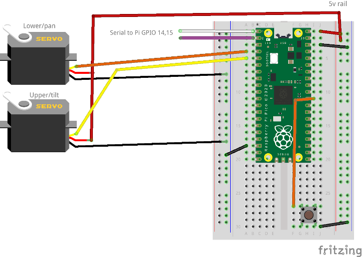
A 9G servo can be connected to a Pico, using 5v VBUS (Pin 40) and any GPIO pin for the PWM signal. I have used GPIO2 and GPIO3 for the lower and upper servo as shown in the diagram below. I have also added a reset button between GND and pin 30 (RUN), which is useful if anything goes wrong.
With the following code, both servos will be put through a range of angles and can be used to check performance. Attaching to the pan/tilt mount at this stage could cause a hardware collision:
# Import libraries
from machine import Pin
import machine
import time
import json

debugOut = True       # Use dprint(str) rather than print(str), set to false to prevent print output

hwData={}             # Build dictionary of hardware data to return current status to Pi
# List of attached servos as array, [pin,min angle, max angle, calibrarion angle]
# Leave blank if no servos
servos=[ [2,15,165,8],    # Pan servo (index 0)
         [3,40,175,0] ]   # Tilt servo (index 1)
servoPWM=[]          # Array of PWM objects for each servo

# ********* Functions *****************
def dprint(str):
    if(debugOut):
        print(str)
# End of debugPrint

# Servo functions
def setServoCycle (obj, pos):
    obj.duty_u16(pos)

def setServoAngle (s, a):
    d = int(a/180*8000+1000)
    #dprint("Angle=",a,"d=",d)
    setServoCycle(servoPWM[s], d)


# ******** Main code ******************

dprint("Hello from pico slave")

# Initialise servos if present
if(servos==[]):
    dprint("No servos defined")
else:
    i=0
    for srv in servos:
        dprint("Init servo on pin {}".format(srv[0]))
        # Create PWM object
        p=machine.PWM(Pin(srv[0]))
        p.freq(50)
        # Add to array
        servoPWM.append(p)
        # Init in mid position
        setServoAngle(i, 90);
        i+=1

# Test by taking each servo through a range of angles
for i in range(len(servoPWM)):
    for a in [30,120,90,10,170,90]:
        setServoAngle(i,a)
        time.sleep(2)
At the start of the code, each servo is defined with a minimum angle, a maximum angle and a calibration angle. At the moment they are ignored, we need to determine optimum values for each one but before we can do that, we need a way to send the desired angle to each servo. That means enabling serial communication.
It is also worth noting that in the libraries on the main Pi, I built them to be quite dynamic and the hardware location of each bit of hardware was passed on initialisation. Now these hardware values are hard coded onto the Pico. While they could be passed on first contact over serial, it is far easier to encode them directly onto the Pico software.
Serial communications
A code archive for this stage of the project can be found in the post archive on GitHub: blogArchive/post5/. Removing the servo test code and adding in the serial communications part from the previous post, a main loop can be added:
# Main loop
while True:
    if uart.any():
        msg=receiveData()
        dprint("Message received: \"{}\"".format(msg))
        if(msg=="quit"):
            checkSensors=False
            break
        if(msg=="ping"):
            sendData("beep")
        elif(msg=="dataRequest"):
            # Return whole data array as JSON
            sendData("null")
Using a serial to USB device (in my case, a Particle Debugger), I can send the message ‘ping’ and get ‘beep’ in response. I now need to define some commands:
- panangle,a – Change the pan servo to angle a
- panleft,a – Change the pan angle by a degrees (-a to turn right)
- tiltangle,a – Change the tilt angle to angle a
- tiltup,a – Tilt up by a degrees, (-a to tilt down)
- servoangle,s,a – Change servo number s to angle a
- servoleft,s,a – Change servo number s angle by a degrees
The latter two functions are generic versions of the first two and will allow additional servos to be added in the future.
Now on receipt of a message, the string is split into an array on every comma, into the variable csvin. The first element should be the command part, and using the pop(0) function this is removed off the start of the array, leaving only an array of arguments (which may be empty) and the command assigned to the variable cmd. Adding the commands into the large if-else, converting the strings to int, we can set the angles for each servo by calling a single function. Further checks are needed, setting the angle on a servo that does not exist will cause an array index failure.
        if(cmd=="quit"):
            break
        elif(cmd=="ping"):
            sendData("beep")
        elif(cmd=="panangle"):
            setServoAngle(0,int(csvin[0]))
        elif(cmd=="tiltangle"):
            setServoAngle(1,int(csvin[0]))
        elif(cmd=="servoangle"):
            setServoAngle(int(csvin[0]),int(csvin[1]))
        elif(cmd=="dataRequest"):
            # Return whole data array as JSON
            sendData("null")
To allow us to adjust the angle by a certain amount, we need to keep track of what the angle is set to. The hwData dictionary is defined to track all sensor and other hardware data. On initialisation of the servos, a “servo” section is created, along with an array where index 0 will be the current angle for server 0 etc etc. To facilitate this, the function changeServoAngle has been added:
def changeServoAngle (s, a):
    # Change the angle of servo s by a degrees
    n=hwData["servos"][s]+a
    setServoAngle(s,n)
Here lies a potential problem, we can easily try to push the servo beyond either the hardware limits of the servo itself, or the desired limits as the hardware may collide. This is especially true of the tilt arm which may hit the ultrasonic sensor. An update to setServoAngle takes into account the limits set on initialisation. It also checks for the index out of range error.
Before setting the servo duty cycle, a calibration angle is applied (see below). This does mean that with calibration you can potentially take the servo beyond the desired set limits. It has been left like this so 90 is still the central angle.
def setServoAngle (s, a):
    # Check servo is in the range of defined servos
    if(s<len(servoPWM)):
        # Is fine, check angle is in range and if not adjust
        # to min or max value

        if(a<servos[s][1]):
            a=servos[s][1]
        if(a>servos[s][2]):
            a=servos[s][2]

        # Add calibration angle
        a=a+servos[s][3]

        d = int(a/180*8000+1000)
        dprint("Angle={}, d={}".format(a,d))
        setServoCycle(servoPWM[s], d)
        # Updata hardware data array
        hwData["servos"][s]=a
# End of set servo angle
The pan/tilt mount
I constructed the pan/tilt mount using OpenSCAD, and it was designed to be as minimalist as possible. It consists of a base with space to hold a 4 prong servo arm, and a retaining plate goes on top to hold it. Four screw holes through both of these hold them together and attach the servo to the robot chasis.
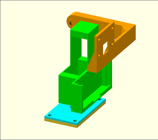
The lower servo goes into this base plate and the whole assembly sits around this upside down servo. This would not be ideal for any great load, but the whole mount is quite light.
The main body is just two rectangular enclosures, using as little plastic as possible to hold the two servos together. It has a slot for inserting a HC-SR04 servo on the front. In the future it may be worth making this taller so the camera arm has greater clearance to the ultrasonic sensor.
Finally an arm is attached to the upper servo and it is to this the camera is mounted. The length of this arm can be changed with variables in the camArm module in the SCAD file. Also in that file, toggling variables such as showBasePlate, will turn certain components on and off.
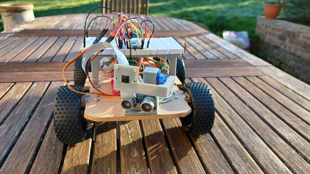
The SCAD file and STL models can be found in the 3d_prints section of the GitHub repository. In addition to the camera mount, I started to run into a problem where there was insufficient space for a Pico and breadboards after guessing an initial size for the robot chassis and getting it a bit too small. elevatedBBholder.stl will give a raised platform allowing part of the Pi and other hardware such as the motor controller to sit underneath, pictured in the main image at the top of this post.
Each servo should push into the rectangular slots, though a drill may be needed to open up the screw holes a little more. I did need to buy a longer camera cable.
Calibrating and limiting
Set the servos to 90° and assemble. Start picoSlave_nothread.py on the Pico and first try the command panangle,90 over the serial console. Change angles until the sensor and camera point forward. I found an angle of 76 worked, so needed and angle of -14 (90-76) to set the camera straight. Put this at the end of the array defining the pan servo and restart. You should find a panangle of 90 now points straight forward. Using the panangle command again, find a maximum and minimum angle you wish to allow the pan servo to turn and put these in as the second and third elements in the array. I found 25 and 150 worked well.
Now repeat the process with the tilt angle. This can be slightly easier as it is best to set the tilt to 90° and then attach the camera arm. However here you need to be careful with tilting down as the camera can hit the ultrasonic sensor. Send multiple tiltangle commands slowly until you find upper and lower limits for the camera arm. A low angle is straight up.
The end result was my calibration and limiting of:
servos=[ [2,25,150,-14],    # Pan servo (index 0)
         [3,30,120,0] ]   # Tilt servo (index 1)
This defines two servos on pins 2 and 3. The first servo (pan) has a limit of 25° to 150°, and a calibration of -14°. The tilt servo didn’t need further calibration so has a zero angle, but has limits set between 30° and 120°.
Connecting to the Pi
So far I have been using a serial cable direct to my PC, but now is time to connect it to the Pi. As described in my last post, the Pi and Pico must have their GNDs connected, then GP0 (Tx) on the Pico connects to GPIO15 (Rx) on the Pi and GP1 (Rx) to GPIO15 (Tx).
Once connected, communications can be tested direct from the command line with screen /dev/ttyS0 115200. However there is an issue with this. At normal typing speed the pico will detect input as a single character at a time and ignore. Using copy and paste, commands from a text editor can be sent. While not ideal, it is useful as a quick test. Use CTRL+A,k, to quit.
Once we know that is working, we can create three basic functions to send, check and receive from the Pico, in pyroverlib.py:
	# Serial functions
	def sendToPico(self, msg):
		# Send over serial port to pico
		data=msg.encode('UTF-8')
		self.sport.write(data)

	def checkSerial(self):
		# Check if there is data in the serial queue
		if(self.sport.in_waiting>0):
			return True
		else:
			return False

	def getFromPico(self):
		# Receive from pico or timeout
		sport=self.sport
		timeoutTime=time.time()+self.picoTimeout
		if(sport.in_waiting>0):
			rawIn = bytearray()
			dataIn = ""
			while (sport.in_waiting > 0 and time.time()<timeoutTime):
				# Read until we get a line ending
				rawIn += sport.read_until()

				# Raw data is a byte stream, convert
				# Need to use a try/except as control characters may cause an issue
				try:
					dataIn = rawIn.decode('utf-8').strip()
					#print("  Incoming :", dataIn)
				except:
					print("Unable to decode")
					return ""
			return dataIn

		else:
			# Queue was empty, return empty string
			return ""
	# End of getFromPico
Adding calls to these functions in driveByQueue.py can allow us to test panning the camera, or sending the command ping and displaying the returned string “beep”, proving communications function.
This doesn’t really provide anything useful except being used to test comms, but now the basics are running, we can expand on it.
Improving the communications process
The above functions allow sending of a message to the Pico, checking if a message is waiting and then pulling the return message if required. We need to keep the Pi as efficient as possible. There is little point offloading the checking of sensors and servo handling to a Pico slave device if the Pi then sits and waits for a response. An alternate method is to use ‘fire and forget’ commands. The Pi sends commands to the Pico, the Pico executes them and then sends back data when ready. The Pi assumes all the data is relatively up to date and never hangs waiting for one particular sensor.
There are flaws with this if a fast dynamic response is needed as the data may be out of date. However what we can do is in PiRoverLib, start a thread on launch which monitors the serial queue. When data is ready then this replaces all data in a Pico branch of the main data dictionary structure, along with a receive time stamp.
Now, rather than the Pi decide to check the ultrasonic sensors (to be added later), the Pico checks on a regular basis, updates the Pi with the latest results and the Pi assumes that any data it has is the latest, but it can double check the age. If this does become too old, it can shutdown and send an error.
To work successfully, the Pi must send all messages as a JSON data structure. Including the response to ping. Rather than return ‘beep’ this becomes ‘msg: “beep”‘ in just one branch. As nothing will overwrite this, beep and a timestamp would be more useful. As the system progresses, ping becomes less useful.
Within the Pico, the function sendhw() is added to convert the hwData array into JSON and send it over the serial line. A variable ‘activate‘ is initially set as false. When sent to true, this will send serial data at a frequency of sendFreq, in milliseconds. On initialisation, the Pi must start send the message ‘activate‘ to begin regular updates. On power up, the Pico will boot and start working far quicker than the Pi. There is no point in it immediately sending unwanted data down the serial line if the Pi is not going to do anything with it. This will also start sensor polling. ‘deactivate’ will terminate sensor reading and sending.
The Pi receive thread
As we don’t want the Pi sitting waiting for a response from the Pico, we can create a thread that constantly checks for data coming from the Pico, using the Python Thread library. As the most basic test, picoRthread() is the receive thread, in the example below it sits and prints ‘picoRthread’ every second, until the variable ‘activated’ is set to False. Calling picoActivate() will launch this thread, while picoDeactivate() will change ‘activated’ in order to terminate the thread again. To call these, functions have been added to driveByQueue.py.
	def picoRthread(self):
		# Pico receive thread. Will sit in a loop waiting for serial data from the Pico
		# Then add it to the main data array
		# Also sends activate to the Pico to start it's loop
		self.activated=True

		# Set to activated
		while self.activated:
			print("picoRthread")
			time.sleep(1)

		print("picoRthread ended")
	# End of picoRthread

	def picoActivate(self):
		# Starts the picoRthread
		print("Activating pico and starting thread")
		picoThread = Thread(target=self.picoRthread)
		picoThread.daemon = True
		picoThread.start()

	def picoDeactivate(self):
		# Sends deactivate to the pico and stops the thread by setting activated to false
		self.activated=False
After this is proven to work, the picoRthread can be improved by having it read serial data, converting the JSON to a dictionary and adding this into the rdata structure with a timestamp.
	def picoRthread(self):
		# Pico receive thread. Will sit in a loop waiting for serial data from the Pico
		# Then add it to the main data array
		# Also sends activate to the Pico to start it's loop
		self.activated=True

		# Start pico loop
		self.sendToPico("activate")

		# Set to activated
		while self.activated:
			# Check for serial input
			if(self.sport.in_waiting>0):
				dataIn = self.getFromPico()
				#print("** Got data **")
				#print(dataIn)
				if(dataIn!=""):
					# dataIn is a string, convert to JSON
					jsonIn = json.loads(dataIn)
					#print(jsonIn)
					# Add timestamp
					jsonIn["timestamp"]=time.time()
					self.rdata["pico"]=jsonIn
					print(self.rdata)

			time.sleep(0.05)

		print("picoRthread ended")

	# End of picoRthread
Adding pan/tilt functions
The above builds a framework from which we can expand to implement sensor and hardware control. For each new function on the Pico, we need a function in piroverlib.py to send a command string to the Pico. So long as this command writes to it’s data array, that data will be passed back to the Pi when ready.
Adding pan/tilt controls to web control
Once a few commands have been established, buttons can be added to the web drive page, and using the webToQueue.py script in web/cgi-bin, the new pan and tilt commands can be sent. Essentially there is a long chain of commands built:
Web button -> webToQueue.py -> driveByQueue.py -> piroverlib.py -> Pico
Initially this will not report data back as there is no way to send an ‘activate’ command from the web. This could be added, or driveByQueue.py has been modified to be started with a ‘-a’ argument. This will automatically start the Pico thread.
Running independently
The one task remaining is to allow the rover to run independently. Currently the Pico powered from a PC USB port and the application has to be started manually. In Thonny, select ‘Save copy..’, save to Pico and name the file ‘main.py’. Each time this file is changed, it needs to be uploaded to the Pico in this way.
The next consideration is how to power the Pico. Under the schematic diagram in the Pico Datasheet, VSYS (pin 39) has a diode between it and the USB connector. With a voltage regulator on this pin, it can accept 2-5v while avoiding sending an external power source up the USB lead to a PC.
The MDD3A motor driver has a 5v output pin designed to help drive low power microcontrollers. Feeding this to VSYS gives us a way to power the Pico from the onboard battery, without the need for an additional voltage regulator.
Final results
On completion, the rover can now be driven from a web panel with the robot-eye-view streaming back. While a long way from being autonomous, it makes a fun remote control car. It is a little clunky to start as driveByQueue.py must be started manually in advance, and the streamer started with bin/streamer.sh start. An application launcher would be a welcome addition in the future. Currently the Pico only reports data back every 5 seconds. Without active sensors, this is fine.