For the background of this project, see the main page. This details the basics from getting the hardware together and making a robot that can do a very basic driving demo.
Hardware
A full inventory of hardware used will be added as the project expands. All the hardware listed below is not used in this post, but the list is used as one complete inventory of hardware and will be updated as the project progresses.
- Raspberry Pi 3B
- Camera v1.3 (v2 was in short supply and quite expensive at the time)
- Cytron MDD3A 3A 4V-16V DC Motor Driver
- 4 x Zhengk ZGA25RP 12V 100RPM brushed DC motor
- 4 x 87mm wheels
- 6 x 18650 batteries
- 3S 11.1V 12.6V 25A W/Balance 18650 Li ion Lithium Battery PCB Protection Board
- 2 x SG09 servos (Longrunner)
- 1 x Raspberry Pi Pico
- 1 x tactile breadboard push button
As the brains of the project, I chose a Raspberry Pi 3B. I wanted the power and versatility of a linux based operating system, that would support a camera, but also be reasonably efficient on the battery. The Pi is a natural choice and while later models are far more powerful processing wise, the 3B has lower power consumption. I also wanted onboard wireless and BLE, which the older models do not have.
Looking through the range of motors at The Pi Hut The ZGA25RP motor looked to be a nice choice. While cheaper plastic motors are available, to be able to cope with the rougher terrain in the garden and have a bit of power, I opted for a metal gear 12V motor. At 2W and 12V, each motor draws 0.16A, so a 3A motor driver board should be sufficient. A number of other projects have said that if you buy cheap motors you will regret it. With the wheels and the motor driver, this was the most expensive part of the project. Note that controlling the steering of a 4WD fixed wheel rover can be difficult. The design may change to driving wheels and a third balance wheel. Money could be saved by only buying the two motors initially.
There are a huge range of motor drivers out there, but the Cytron MDD3A looked like it would do the job and was only GPB £8. If I need something better, I’ve not lost that much. The 87mm wheels were the biggest in stock. These should be able to cope with my rather uneven lawn.
Setting up the Pi
There are many web resources detailing how to install the OS on a Pi, there is no need to repeat them here. Before setting up the OS, the camera was installed on the board.
- Basic Pi build, write Raspbian image to the card
- I went for a lite version, but if you want to run the likes of Scratch, a desktop version may be more appropriate
- Mount first partition, copy in a wpa_supplicant.conf and
touch ssh - Boot and
ssh pi@raspberrypi.local sudo raspi-config- Set hostname
- Interface: Enable camera, I2C
- Set time zone
- Advanced: Expand file system
- Finish & reboot
apt update; apt upgrade- Test the camera with
raspistill -o testpic.jpg
Getting the motors running
The essential part of any roving robot project is getting it rolling, starting with making the motors turn. Soldering wires onto the motor, touching them to a 12v power supply makes them spin. So far so good. Motors are connected to the MDD3A motor driver as shown in the diagram from Cytron:

Without connecting this to the Pi, the next test we can do is connect up two motors and press each of the four buttons. They should rotate in different directions when the A and B buttons are pressed.
All the test code is available in the Github repository, under the hw_testing subdirectory.
Now we know the motors work, they can be connected to the Pi. The 5v and GND connector on the motor driver can be used as a power supply for up to 200mA. This is far too small to try and run our Pi, so do not connect the 5V pin. To allow speed control of two channels we need to use both the Pi PWM channels by connecting to appropriate pins. Connect as follows:
| MDD3a motor driver | Raspberry Pi | PWM |
|---|---|---|
| M1A (motor 1 A) | GPIO 18 (pin 12) | 0 |
| M1B (motor 1 B) | GPIO 12 (pin 32) | 0 |
| GND | Any GND (pin 39) | |
| M2A (motor 2 A) | GPIO 13 (pin 33) | 1 |
| M2B (motor 2 B) | GPIO 19 (pin | 1 |
The motor driver documentation defines the following input logic:
| IN A | IN B | Motor |
|---|---|---|
| Low | Low | Break |
| High | Low | Forward |
| Low | High | Reverse |
| High | High | Break |
The test script basicMotor1.py tests this by setting the GPIO pins of the two motors as outputs then to set forward motion:
print("Forward")
GPIO.output(M1A, GPIO.HIGH)
GPIO.output(M2A, GPIO.HIGH)
As the ‘B’ pin is already low, we get forward motion at full speed. A bit of paper or some blu tack on the motor can be a good way of seeing the motion. All four logic conditions are tested.
Setting the motors to high or low is all very well if we only want our robot to stop or go at full speed. If we want to control the speed more carefully we need to use PWM to change the amount of power we are sending. We are not actually sending a variable voltage, a description of what is actually happening is on Adafruit Learn. If we create a PWM object assigned to a pin, set a frequency of 1000 then the duty cycle (0-100) forms the percent of power we will run the motors at. Create the PWM object on the A pin (with B set to LOW) to take the motor forward, or the B pin to reverse it.
basicMotor2.py takes the M1 motor and slowly spins this up to full speed by increasing the duty cycle, using this snippet of code. The motor is then reversed:
# Set up PWM channel
pwmA = GPIO.PWM(M1A, 1000)
pwmA.start(0)
for duty in range(0,101):
    pwmA.ChangeDutyCycle(duty)
    time.sleep(0.1)
time.sleep(2)
print("Stopping")
pwmA.stop()
Note: This uses software PWM, as the project progresses hardware PWM may prove a better option. By using the hardware PWM pins we should not need a wiring change. There is a description of the difference here.
There is a lot of repeated code in these two demonstrations. basicMotor3.py defines a pwmMotor class. Using this to create an object for the left and right motor, this class will form the basis of a library later full versions of code. The following functions are defined:
- init – The standard class initiator, call with
m = pwmMotor(<A pin>, <B pin>) stopPWM()– Used internally to disable the PWM object running on a pinstop()– Stop the motors spinningfull(sp)– Any positive value will run the motors at full power forward, any negative value will be full power in reverse.setSpeed(sp)– Set a speed as a percentage. A negative value runs in reverse.
The script calls a few of these functions to demonstrate their use and show we can run one motor backwards at a different speed to the forward speed of the other motor. As a final test, the other two motors were added in parallel, putting two motors on each output.

Building the chassis
Now it starts to get interesting! The robot needs a chassis to hold it together. There are many different materials which can be used with aluminium or a type of plastic (such as acrylic) being the most popular. Both are strong, light and easy to come by. However for the first prototype, I chose 6mm MDF.
MDF is not a great material to make a chassis from, especially for a robot that will be used outdoors. It can bend under load, warp with moisture or the screw holes break down under vibration. However it has a couple of advantages for a first prototype. It is cheap, it is easy to work with and I had plenty in the shed.
The length of the motors is 55mm including the pins, so I thought 3×55=165mm would be a good width. A reasonable width to length ratio is 1.6, giving a length of 264mm. After adding the motor brackets, I quickly found two things. This is actually quite small. It may suffice for well organised, well planned hardware, but space is limited for a project where I make it up when I go along. Also, because the wheels are so wide, they would not go fully on the shafts without cutting some recesses out, they were catching on the chassis side. Before long a new chassis will be needed but I’ve picked up some design lessons with cheap hardware at even this early stage.
The Pi was secured to the board using adhesive pads, self tapping screws to secure the motor driver and a cheap plastic camera mount (which came with the camera) holds the camera on the front. Holes through the board allow the motor wires to pass through. If I had made these closer to the front and back, I’d have more usable space on the chassis. But as a first prototype, it doesn’t look too bad:

Almost ready to go. Prop the robot up on a box so the wheels are not touching anything and try basicMotor3.py again. The first thing I found was I had the motors on one side wired up the wrong way. Make sure both go forward during the forward test. If the wheels on the left move at the same speed and both the wheels on the right move at the same speed, you are ready for the first driving test.
driveTest1.py will drive the robot forward for 3 seconds at half speed, then reverse for another 3 seconds. It will then go forward turning slightly right, by running the right wheels at half the speed of the left. It follows this by continuing forward by making a left turn. In order to be able to do this, I had to power the Pi from a small 5v power tank (usually used to recharge mobile phones) and run a long cable from the 12v power supply. While not very practical, it moves. I have a basic working robot, milestone one hit.
I did try spinning the robot by running the wheels in the opposite direction but this did not work too well. A number of web resources suggest this can be a problem for four wheel drive robots on carpet. Further investigation is required.
Powering the robot
There are many options for powering a Pi rover robot. Given I decided to use 12v motors, I’m going to need a power supply of around 12v. There are many different RC car batteries on the market at 11.1v which will suffice, though all come with warnings to make sure you do not fully drain or overcharge them. I had a number of 18650 batteries which had been pulled out of old laptop power supplies, so I decided to make my own battery pack to make use of these.
As a basis for the power pack, I followed the Instructables guide ‘DIY Professional 18650 Battery Pack‘. Using the BMS (battery management system) controller board, it handles charging and discharging, giving a level of safety. However I did make some changes to the above design. First I don’t have a spot welder and second, I don’t know how good each individual cell I have is. If one is a bad cell which discharges quickly then I want to be able to quickly swap it out. Also, initially using 3 pairs of 18650s in parallel, I was not sure how long they will last. Will I need to expand this in the near future?
I used the Flexing battery holders on Thingiverse, but slightly altered the design to include a slot to thread in a nickel strip. The SCAD and STL files are in the 3dPrints directory. The batteries were placed in their holders a number of weeks before assembly, fully charged. After a period with no load, all cells still reported over 4v each.
Using tape to bind each battery pair together, a few cm of wire between each pack (so it can be pulled apart again) and an elastic band to hold the control board in place, the end result was a functional but not very professional looking battery pack. If this is sufficient to power the motors for a decent length of time and the cells are good, then this will need a revamp later.

12v is too much to power the Pi and some form of voltage step-down will be required. As it was working fine from a small 5v power tank, I decided to leave that in place for now.
First drive
With the two power packs secured in place on the chassis (with a cable tie and blu tack), it was ready to work free from cables. The end result was a basic working rover robot but with the definite look of an early prototype.
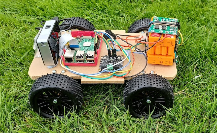
The first drive was unspectacular but a great first step: