The Micro:bit comes with 20 IO (input/output) pins which can be used to connect a range of hardware devices, however if you look at a pinout diagram, you find that 8 of these are used by the LED display and the buttons. If you start using devices which require a lot of pins (such as keypads), then you can quickly run out of usable pins.
One solution is to use devices such as PCF8574 modules which connect to the I2C (19 and 20) pins and will provide 8 additional pins. As you can connect multiple devices to I2C, you can either add more pin expansion modules or other types of device. For example, with a keypad attached to a PCF8574 and an I2C LCD screen, you can attach both to the Micro:bit and only use pins 19 and 20.
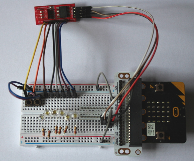
When all onboard switches are set to off, PCF8574 modules usually use the I2C address 0x20. If we connect LEDs to the first six pins of a module (P0 to P5) with 220 or 330 ohm resistors to ground on the other side (as pictured below). Build this circuit but ignore the buttons for now. We can flash all six LEDs with the following code:
# Testing of a IO expanded - PCF8574
from microbit import *

PCF_ADDR = 0x20     # Use the base address of the PCF8574

# I2C send, function to simplify writing
def sendI2C(addr, value):
    # Convert sent value to a byte array, which is
    # required for I2C
    buf = bytearray(1)
    buf[0] = value
    # Send value
    i2c.write(addr, buf)
    # Short delay to send
    sleep(5)

while True:
    sendI2C(PCF_ADDR, 0xFF)
    sleep(1000)
    sendI2C(PCF_ADDR, 0x00)
    sleep(1000)
What is going on here? The PCF8574 has 8 IO pins labelled P0 through to P7. If we want to set the output to one of those pins to high, we need to send it a 1, or a zero to be low. Where as with the normal Micro:Bit IO pins, we set them individually, with the PCF8574, we set them all in one go by sending a single byte containing all the information we need. An I2C write to the modules address with the value 0xFF means send all 1s, or turn all the IO pins on. Sending 0x00 means turn all the IO pins off. The above code flashes all the LEDs.
To really understand what is happening and have greater control of the LEDs, we need to understand binary and hexadecimal.
Understanding binary
Binary is another way of counting. We are used to using the numbers 0 to 9 (known as decimal), but in binary we only use 0 and 1. There is a BBC Bitesize module which gives a lot more information into understanding binary. Here we have a very brief description.
In decimal counting, a single digit 0 to 9 is not a lot of use if we want to count higher than 9. To go higher, we use the same digits again, arranged into columns increasing in value as we go from right to left. We start with units, then tens, hundreds, thousands and so on. We think of the number 157 as:
| 1000 | 100 | 10 | 1 |
| 0 | 1 | 5 | 7 |
We are saying 157 is no thousands add 1 x 100 add 5 x 10 add 1 x 7. You will also notice that the columns as you go from right to left increase by a multiple of 10 each time.
In binary, as we only have the two digits 0 and 1, the columns increase by a multiple of 2 each time we move one to the left, which means we can think of numbers as:
| 128 | 64 | 32 | 16 | 8 | 4 | 2 | 1 |
| 1 | 1 | 1 | 1 | 1 | 1 | 1 | 1 |
With all numbers set to 1, 1111 1111 in decimal is 128+64+32+16+8+4+2+1, which is 255. If we changed all the values to 0, this would be 0 x 128 + 0 x 64 + 0 x 32 etc. The result would be 0, so in binary and decimal, 0 is the same. (So is 1).
How does this relate to our LEDs? Each of the IO pins is controlled by a single binary digit, so we can think of them all as:
| 128 | 64 | 32 | 16 | 8 | 4 | 2 | 1 |
| P7 | P6 | P5 | P4 | P3 | P2 | P1 | P0 |
| 1 | 1 | 1 | 1 | 1 | 1 | 1 | 1 |
So, looking at the above, we know that 1111 1111 is 255 in decimal, and 0000 0000 is 0, so what would happen if we changed our loop to:
while True:
    sendI2C(PCF_ADDR, 255)
    sleep(1000)
    sendI2C(PCF_ADDR, 0)
    sleep(1000)
Give it a try.
No change. We are setting pins 7 and 6 when we have nothing attached, so why bother? What if we wanted to stop sending to those and only flash the lights on alternate pins with P5 on? What value would we need to send instead of 255? Consider it as a table:
| 128 | 64 | 32 | 16 | 8 | 4 | 2 | 1 |
| P7 | P6 | P5 | P4 | P3 | P2 | P1 | P0 |
| 0 | 0 | 1 | 0 | 1 | 0 | 1 | 0 |
We need to add all the columns where there is a 1, which is 32+8+2. The answer is 42. Try changing this in the main loop and see what happens? What other patterns can you produce?
In python, you can write binary numbers directly, using the prefix ‘0b’. Another way to send the above example would be ‘0b101010’. Give that a try.
Binary Operators
In binary, we have a number of binary operators available. These are functions in the same way we have plus and multiply in decimal. Using these, we can get other effects. You need to be aware that these operate on bytes. A byte is 8 binary digits, so 42 should always be considered as 0010 1010, not just 101010. Our PCF8574 requires a single byte send to cover all 8 IO pins.
| Python notation | Function | Description |
| ~ a | NOT | The inverse of the value of the variable a. All 1s are changed to 0 and all 0 to 1. 0010 1010 becomes 1101 0101 |
| a & b | AND | Applied in a column by column basis. If there is a 1 in the 4th column of ‘a’ and a 1 in the 4th column of ‘b’ then the result will be 1. 0010 1010AND 0110 1001 becomes 0010 1000because there are only 1s in both the 4th and 6th column, counting right from left. |
| a | b | OR | Applied in the same way as AND only there will be a 1 in the result if there is a 1 in ‘a’ or in ‘b’. e.g. 0010 1010OR 0110 1001 becomes 0110 1011 |
| a << b | Left shift | Move all the binary digits to the left ‘b’ number of places, padding the end with zeros. Imagine this as more zeros coming in from the right to shove the numbers up. If we try a left shift of 2 we get 0010 1010 << 2= 1010 1000 |
| a >> b | Right shift | Move all the binary digits in a to the right ‘b’ number of places. Same as left shift only the other way round. 0010 1010 >> 2= 0000 1010The two digits on the right that were pushed out disappear – like pushing them into the bin! |
We can have a bit of fun with these. What if we wanted to create a pattern and flash the opposite? Just assign our pattern to the variable ‘p’ and use the NOT function:
while True:
    p = 0b101010
    sendI2C(PCF_ADDR, p)
    sleep(1000)
    sendI2C(PCF_ADDR, ~ p)
    sleep(1000)
Try changing the pattern.
What if we wanted to flash each light in turn then return to the start? We can work out that to light only the right most light, we need to send a 1 or 0b1, then to only light the next we can send a 2 or 0b10, then 4 or 0b100 etc, but that gets a bit repetitive. All we are doing each time is moving the 1 to the left and we know we have 6 LEDs, so we can keep the code short and use the left shift:
while True:
    # Set the initial pattern, right light on
    p = 1

    # Loop 6 times
    for x in range(6):
        sendI2C(PCF_ADDR, p)
        sleep(500)
        # Shift the pattern 1 place to the left
        p = p << 1
Hexadecimal
So, what about hexadecimal?
Hexadecimal is another numbering system. Rather than use the digits 0-9 or just 1 and 0, hexadecimal has the numbers 0 to 15. Going into double digits gets confusing so we use the letters A to F. In Python, we use the 0x prefix to mean something is hexadecimal. It was this we were using in the original code snippet. There is a BBC Bitesize module on hexadecimal.
| Hexadecimal | Decimal | Binary |
| 0 | 0 | 0000 |
| 1 | 1 | 0001 |
| 2 | 2 | 0010 |
| 3 | 3 | 0011 |
| 4 | 4 | 0100 |
| 5 | 5 | 0101 |
| 6 | 6 | 0110 |
| 7 | 7 | 0111 |
| 8 | 8 | 1000 |
| 9 | 9 | 1001 |
| A | 10 | 1010 |
| B | 11 | 1011 |
| C | 12 | 1100 |
| D | 13 | 1101 |
| E | 14 | 1110 |
| F | 15 | 1111 |
When counting in hexadecimal (or hex for short), the columns go up in multiples of 16. E.g.:
| 256 | 16 | 1 |
| 0 | 2 | A |
In the above, we have 2x 16 + 10 x 1, which is 42 again. We previously used the binary 0010 1010 to represent 42, but look at the table of hex to decimal to binary digits. A 2 in binary is 0010 and a A is 1010. If we put them together 2A = 0010 1010. Basically by looking at each hex digit we can quickly convert between hex and binary without worrying about how man 32s, how many 16s we have etc. This is why programmers often use hex. Computers operate using binary and hex gives a very short hand notation for writing binary.
In the very first example, we set all the outputs to 1 by sending 0xFF. Can you see why that works?
Reading inputs
What if we wanted to attach some buttons? Can we read inputs? Yes. Now connect up P6 and P7 to buttons as in the picture above. If we write a 1 to each of these pins to put them in a high state, connect then to one side of a button and the other side to ground, when you press the button, it will be pulled low and turn to zero.
The following code writes a 1 to P6 and P7, then reads it back and prints the value back as a decimal. If you convert the binary, 0b1100 0000 is 192. If no button is pressed it will return a 192. However if you press the left button, the left most bit will turn to zero. This is 128 less, so 64 will be reported on the REPL console. If you press the right button, 128 should be reported and both will set the returned state to zero.
# Testing of a IO expanded - PCF8574
from microbit import *

PCF_ADDR = 0x20     # Use the base address of the PCF8574

# I2C send, function to simplify writing
def sendI2C(addr, value):
    # Convert sent value to a byte array, which is
    # required for I2C
    buf = bytearray(1)
    buf[0] = value
    # Send value
    i2c.write(addr, buf)
    # Short delay to send
    sleep(5)

def readI2C(addr):
    # Read in as a single byte and return
    v = i2c.read(addr, 1)[0]
    return v

# Input test
# Set P6 and P7 to high
buttonSet = 0b11000000
sendI2C(PCF_ADDR, buttonSet)
while True:
    v = readI2C(PCF_ADDR)
    print ("Button input = ", v)
    sleep(1000)
If you want to look at the returned value as binary or hex, use bin(v) or hex(v) in the print statement. Note that it will always trim leading zeros off the binary string, so when you press the left button, the binary string shrinks by 1 bit.
Combining Input And Output
That is all very well, but now the LEDs are broken. If we send our LED pattern the buttons will stop working. If we send our pattern to set the button state, the LEDs will stop working. If you can set the button states and the LEDs together, when you read back the values, you will also read back the LED state, meaning our 192, 128 and 64 for the buttons no longer hold true. Their values will be higher depending on which LEDs are currently showing. How can we handle both?
This is where the bitwise operators come in very useful. An OR essentially combines two binary values together. If we have one value for our LED state and one value to set the buttons, then OR them together before sending, the two values are combined and we can have both. For example if we want the third LED from the right showing and to set our button states we can can see what happens with the following table:
| Value | P7 | P6 | P5 | P4 | P3 | P2 | P1 | P0 | In Hex | |
| LED set | 0 | 0 | 0 | 0 | 0 | 1 | 0 | 0 | 0x04 | |
| OR | Button set | 1 | 1 | 0 | 0 | 0 | 0 | 0 | 0 | 0xC0 |
| Combined | 1 | 1 | 0 | 0 | 0 | 1 | 0 | 0 | 0xC4 |
What about reading values back? The AND function is often described as a mask. If we only want to know the state of P7 then we can make a binary string where only the left most bit is set to 1. If we AND this with the returned value we ‘mask’ out the other bits and can only look at the state of the one bit. If the whole value is zero then the button is pressed and if the button is not pressed, it should be 128. However we do not really care what the value is, just if it is not equal to zero. In the following table, P7 is being pressed but P6 is not.
| Value | P7 | P6 | P5 | P4 | P3 | P2 | P1 | P0 | In Hex | |
| Returned value | 0 | 1 | 0 | 0 | 0 | 1 | 0 | 0 | 0x44 | |
| AND | P7 mask | 1 | 0 | 0 | 0 | 0 | 0 | 0 | 0 | 0x80 |
| Result | 0 | 0 | 0 | 0 | 0 | 0 | 0 | 0 | 0x00 |
Can you see what the result would be if P7 were not being pressed?
Lets put this into our code. Reading the result on the REPL console is slow, so as we have made sure we can still use the LED display on the Micro:Bit, lets make use of it. If we say the left button on P7 has a value of 2 and P6 has a value of 1. We can say if no button is pressed show a 0, if P7 is pressed, show a 2, if P6 is pressed show a 1 and show a 3 if both are pressed. Meanwhile, show our marching LEDs from the previous example. Also use hax values as this is more common when coding. Change the main loop to:
# Input test
# Set P6 and P7 to high
buttonSet = 0xC0
while True:
    # Set the initial pattern, right light on
    p = 0x01

    # Loop 6 times
    for x in range(6):
        # Combine the two values with an OR and
        # send to the Micro:But. Use the variable
        # s for send
        s = buttonSet | p
        sendI2C(PCF_ADDR, s)

        # Shift the pattern 1 place to the left
        p = p << 1

        # Check the button state, use the variable
        # bState. Initially set it to zero
        bState = 0

        # Read a value in from the PCF8574
        v = readI2C(PCF_ADDR)

        # If that value AND the binary 1000 000 is
        # zero then button on P7 is being pressed
        if( ( v & 0x80 ) == 0 ):
            # Button is pressed, add 2 to bState
            bState = bState + 2

        # Now do the same for P6
        if( ( v & 0x40 ) == 0 ):
            # Button is pressed, add 1 to bState
            bState = bState + 1

        # Show the button state on the display
        display.show(bState)

        sleep(500)
We can make the button check and the display set even more efficient with the following code. We could even combine everything to one line if we wanted. Can you describe what is happening here (I’ve deliberately left the comments out) and can you make this a one liner? Remember, you can use the REPL console for debugging and print values as binary to see what is going on, e.g. print ("v = ", bin(v)). A pencil and paper may help too.
# Input test
# Set P6 and P7 to high
buttonSet = 0xC0
while True:
    # Set the initial pattern, right light on
    p = 0x01

    # Loop 6 times
    for x in range(6):
        # Combine the two values with an OR and
        # send to the Micro:But. Use the variable
        # s for send
        s = buttonSet | p
        sendI2C(PCF_ADDR, s)

        # Shift the pattern 1 place to the left
        p = p << 1

        # Check the button state, use the variable
        # bState. Initially set it to zero
        bState = 0

        # Read a value in from the PCF8574
        v = readI2C(PCF_ADDR)

        a = v >> 6
        b = ~ a
        bState = b & 0x03

        # Show the button state on the display
        display.show(bState)

        sleep(500)