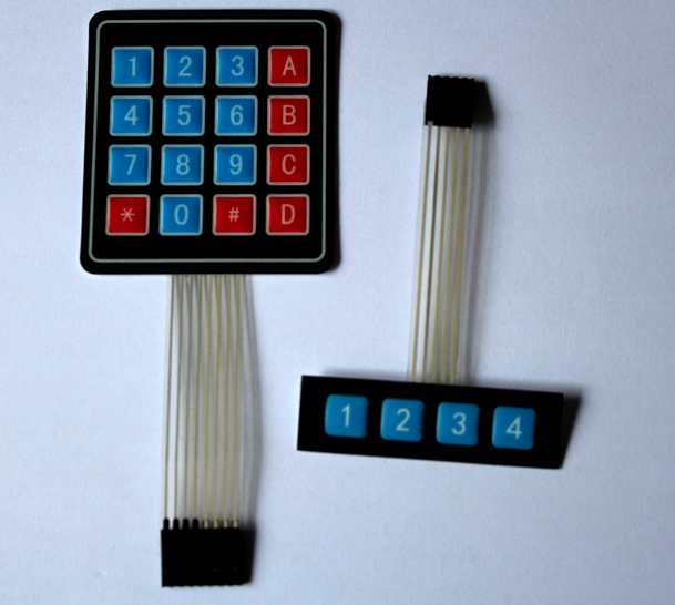
Keypads make a convenient way to add lots of buttons to a Micro:bit and they come in a range of sizes. The type above are known as membrane keypads. They have a sticky back, are lightly waterproof and can be wiped clean.
4 x 1 Keypad
A 4 x 1 keypad is named as it is 4 buttons in 1 row. It comes with a ribbon connector cable, with 5 pins. There is one pin for each key and one for ground. The wiring for these can always differ, so it is worth checking. Often ground is on a strip of cable on it’s own. The connector usually had a small number on each end denoting the pin number. On the keypad pictured above, the pinout, going from left to right is:
| Pin | Function | Micro:bit |
| 1 | Ground | Gnd |
| 2 | Key ‘2’ | pin0 |
| 3 | Key ‘1’ | pin1 |
| 4 | Key ‘4’ | pin2 |
| 5 | Key ‘3’ | pin8 |
You can see from the above the wiring does not go 1, 2, 3, 4 as you may expect. Sometimes these keypads can have different symbols or be blank.
Have a quick read up on Micro:bit buttons to see how a basic push button works on a Micro:bit. If we use a variable for each button and assign it to a pin we can set an internal pull up resistor then use read_digital() to get the state. The following code will show on the display which button is being pressed:
# 4x1 keypad

from microbit import *

# Define our wiring. The 5th connection goes to ground
key1 = pin1
key2 = pin0
key3 = pin8
key4 = pin2

# Set internal pullup resistor
key1.set_pull(key1.PULL_UP)
key2.set_pull(key2.PULL_UP)
key3.set_pull(key3.PULL_UP)
key4.set_pull(key4.PULL_UP)

while True:
    if ( key1.read_digital() == 0 ):
        display.show("1")
        sleep(500)
        display.clear()
    if ( key2.read_digital() == 0 ):
        display.show("2")
        sleep(500)
        display.clear()
    if ( key3.read_digital() == 0 ):
        display.show("3")
        sleep(500)
        display.clear()
    if ( key4.read_digital() == 0 ):
        display.show("4")
        sleep(500)
        display.clear()
There is a lot of repeated code there and the program does not scale well if we were to use a different sized keypad. We can take advantage of arrays in Python to avoid writing the same code over and over again. Read up on arrays at w3schools. Rather than use a straightforward array of single values, we use a two dimensional array. Each value in the array keypad is a small array itself, with two elements, the pin number and the value. Lists start at 0, so we can access the value of the second pin with keypad[1][1].
# 4x1 keypad

from microbit import *

# Create our pinout as a list. Use pairs of values
# of [ pin, value ]
keypad = [ [pin1, "1"],
           [pin0, "2"],
           [pin8, "3"],
           [pin2, "4"] ]


# Set internal pullup resistor, looping through the list
for k in keypad:
    k[0].set_pull(k[0].PULL_UP)

while True:
    # Loop through list checking for keypress
    for k in keypad:
        if ( k[0].read_digital() == 0 ):
            display.show(k[1])
            sleep(500)
            display.clear()
4×4 Keypads
We learned above that smaller keypads have one pin for each button, plus an additional pin for ground. A 2 button keypad will have 3 pins, a 4 button keypad has 5 pins. A 4×4 keypad has 16 keys, so it should have 17 pins, right? No, it only has 8 pins, so what is going on here?
The image below shows a circuit diagram of a 4×4 keypad:
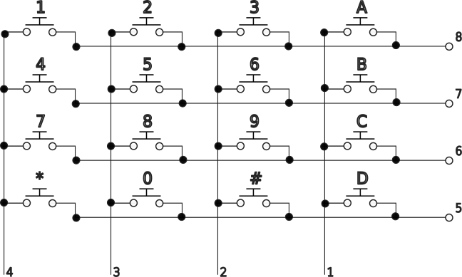
The wiring forms a matrix. If you trace the circuit through, you can see if the ‘5’ key is pressed, a connection is formed between pin 7 and pin 3. If we can detect these connections then we can work out what button is being pressed.
Rather than use 8 IO pins on the Micro:bit, we can use a PCF8574 module to easily plug in the keypad and use some binary or hex to quickly work out what buttons are being pressed. Read up on the PCF8574, binary and hex here. Connect the keypad to the PCF8574 board making sure pin 1 on the keypad goes to p0 on the board. P0 is labelled on the underside.
The PCF8574 has four connections, connect Vcc to 3v and GND to GND. The remaining two connections are for the I2C bus. SDA goes to pin 20 and SCL goes to pin 19. It does not matter if you already have a device plugged into these two pins on the Micro:bit. As I2C is a bus technology, it can support multiple devices, each with it’s own address. The three small switches on the PCF8574 are used to change the address of the board, leave then all as ‘Off’.
On the PCF8574, if a pin set to be high is connected to a pin set to be low, then the high pin will be dragged low. If we set all the pins to high, except one row (for example pin 5), we can detect a button press on that row by a pin 1 to 4 also going low. We can write one value to set the pins then read it back, if there are no key presses on that row the value will be the same. If the value is different then something is being pressed. Cycle through pins 5 to 8 in turn setting each to be low then inspect to see if something is pressed and return what.
We can follow the circuit diagram and make a table of what the two low values should be for each key press. As this forms an 8 bit binary string, we can also shorten each of these to give a unique hex value for each pin.
| Key | P8 | P7 | P6 | P5 | P4 | P3 | P2 | P1 | Hex |
| 1 | 0 | 1 | 1 | 1 | 0 | 1 | 1 | 1 | 0x77 |
| 2 | 0 | 1 | 1 | 1 | 1 | 0 | 1 | 1 | 0x7B |
| 3 | 0 | 1 | 1 | 1 | 1 | 1 | 0 | 1 | 0x7D |
| 4 | 1 | 0 | 1 | 1 | 0 | 1 | 1 | 1 | 0xB7 |
| 5 | 1 | 0 | 1 | 1 | 1 | 0 | 1 | 1 | 0xBB |
| 6 | 1 | 0 | 1 | 1 | 1 | 1 | 0 | 1 | 0xBD |
| 7 | 1 | 1 | 0 | 1 | 0 | 1 | 1 | 1 | 0xD7 |
| 8 | 1 | 1 | 0 | 1 | 1 | 0 | 1 | 1 | 0xDB |
| 9 | 1 | 1 | 0 | 1 | 1 | 1 | 0 | 1 | 0xDD |
| A | 0 | 1 | 1 | 1 | 1 | 1 | 1 | 0 | 0x7E |
| B | 1 | 0 | 1 | 1 | 1 | 1 | 1 | 0 | 0xBE |
| C | 1 | 1 | 0 | 1 | 1 | 1 | 1 | 0 | 0xDE |
| D | 1 | 1 | 1 | 0 | 1 | 1 | 1 | 0 | 0xEE |
| * | 1 | 1 | 1 | 0 | 0 | 1 | 1 | 1 | 0xE7 |
| 0 | 1 | 1 | 1 | 0 | 1 | 0 | 1 | 1 | 0xEB |
| # | 1 | 1 | 1 | 0 | 1 | 1 | 0 | 1 | 0xED |
Similar to an array in Python, we can also use a data structure called a dictionary to store these hex values. An array uses an index number 0, 1, 2… etc for each entry, where as a dictionary can use anything else, even text. Read up here. If we make a dictionary with each of the above hex values as keys and the key symbol as the value, e.g. keys[0xBB] = "5", we can quickly look up what key is pressed from the value returned from the PCF8574 board.
This gives us a process we can follow to detect key presses:
- Create a variable with all the bits high except pin 5.
- Send variable to the PCF8574 to set the pins.
- Read data back from the PCF8574 and store in a variable.
- If the value sent is different to the value received, a key on that row is being pressed
- Lookup that value in the dictionary and return the key press
- Skip to the next row and repeat if no press detected
This is done in the readKeypad function in the following code:
# 4x4 keypad
from microbit import *

PCF_ADDR = 0x20     # Use the base address of the PCF8574

# I2C send, function to simplify writing
def sendI2C(addr, value):
    # Convert sent value to a byte array, which is
    # required for I2C
    buf = bytearray(1)
    buf[0] = value
    # Send value
    i2c.write(addr, buf)
    # Short delay to send
    sleep(5)

def readI2C(addr):
    # Read in as a single byte and return
    v = i2c.read(addr, 1)[0]
    return v

def readKeypad():
    # Define array of keypress values
    # Curly brackets are a dictionary as we are not
    # using consecutive index values
    keys = {}
    keys[0x77] = "1"
    keys[0x7B] = "2"
    keys[0x7D] = "3"
    keys[0xB7] = "4"
    keys[0xBB] = "5"
    keys[0xBD] = "6"
    keys[0xD7] = "7"
    keys[0xDB] = "8"
    keys[0xDD] = "9"
    keys[0x7E] = "A"
    keys[0xBE] = "B"
    keys[0xDE] = "C"
    keys[0xEE] = "D"
    keys[0xE7] = "*"
    keys[0xEB] = "0"
    keys[0xED] = "#"

    # Set the default keypress to be an empty string
    # to mean nothing pressed
    kp = ""

    # Start with a zero on bit 5, all the rest 1
    setState = 0xEF

    for x in range(4):
        sendI2C(PCF_ADDR, setState)
        # Read value back
        r = readI2C(PCF_ADDR)

        # If the return state is different to the set state, a
        # key press has pulled one of the pins, 1-4 low
        if(setState != r):
            # print("setState=",hex(setState),", r=",hex(r))
            kp = keys[r]
            # Return key press
            return kp

        # Move the zero up to the next pin with a left shift.
        # We want to keep the value at 8 bits, so need to AND
        # with FF. Also, a zero will be moved in from the right.
        # OR with 0x01 to set this lower bit.
        # e.g. 1110 1111 << 1
        #   = 11101 1110 & 0xFF
        #   =  1101 1110 | 0x01
        #   =  1101 1111
        setState = ( ( setState << 1) & 0xFF) | 0x01

    # Return keypress value
    return kp

while True:
        # Read from keypad
        kp = readKeypad()
        # Clear if an empty string comes back
        if( kp == "" ):
            display.clear()
        else:
            # Otherwise show
            display.show(kp)
        sleep(200)
Using a dictionary this way also allows you to change the meaning of keys. For example if you were making a calculator you could change the dictionary to return ‘+’ instead of ‘A’. Remember you can use the bin() and hex() functions with print if you want to see what is going on for any stage of the above.