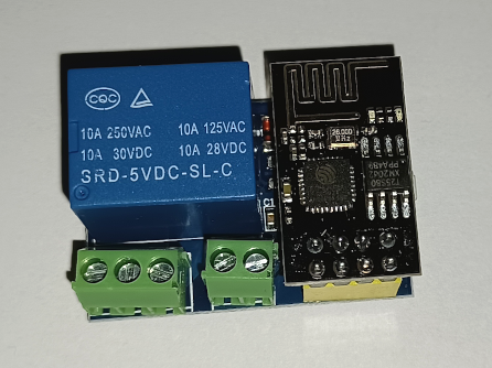
While buying something else, I spotted a small wireless relay module for £5 that looked useful, so I thought I’d buy one to investigate. It consists of a ESP-01s wireless microcontroller and a 5v relay.
Programming the ESP-01s
An ESP-01s can be thought of a bit like a small wireless Arduino, but not having a USB port, you can not program these directly. You can use an Arduino to program it, but I had a FTDI (FT232R) module which I had also been using to program a ESP32. You need to connect GPIO0 to ground when programming, and CH_PD requires 3.3v the same as Vcc. This means you have to use a breadboard or similar as an intermediate to split the wiring.
Connect up as below.
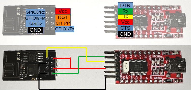
Note the position of the jumper. With the jumper in the lower position, Vcc is 3.3v. With it in the higher position the programmer delivers 5v. With no jumper at all, it will deliver 2.86v, which is enough to make it look like it is working but cause a lot of problems.
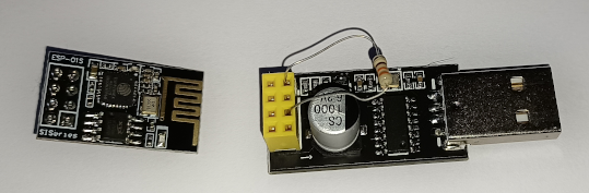
Another option is to use a CH340 programmer, which can often be bought in a bundle with a ESP-01s. However by default this does not go into programming mode as GND and GPIO00 are not connected. There are a number of modifications people have performed adding buttons etc, but a quick way is to insert a resistor between the two pins as pictured. I used a 330Ω, though some are sold with 10kΩ for this purpose. You should remove the unit, remove the resistor and connect it to your computer again to run the uploaded sketch. I found sometimes this worked automatically without removing the resistor, sometimes it did not. I did have to reinsert to enter programming mode again.
Blink
The ESP-01s can be programmed with the Arduino IDE. Under File->Preferences, add (CSV) http://arduino.esp8266.com/stable/package_esp8266com_index.json into the additional boards list. Then under Tools->Boards, select Generic ESP8266 Module. Ensure the port is set correctly and the upload speed is set to 115200.
Start by uploading a blink sketch, to blink the onboard blue LED. The below sketch is an edit of the Blink in the examples directory. LED_BUILTIN can differ from board to board, this modified version forces it to use pin GPIO1. Hit upload (you may want to pull the power to reset the board if you have problems) and wait for it to complete successfully.
Although uploaded, this will not work for three reasons. First, the GND connection to GPIO0 must be disconnected after a sketch is uploaded. Second, as GPIO1 is also the LED and Tx, it will not work while the serial programmer is connected. And finally, the FT232RL module can struggle to supply sufficient power to run the ESP-01s. Connecting to an external 3.3v power supply (ensuring both Vcc and CH_PP are connected to 3.3v) should see the LED blink.
When I was using a breadboard power supply, I created a momentary short. Despite only being a split second, this particular supply had poor quality power regulators. The short caused a fail, at which point it delivered about 11v and little wisps of smoke came out of my ESP0-01. The second one I bought had the internal LED on GPIO2, rather than GPIO1.
#define LED 1

void setup() {
  pinMode(LED, OUTPUT);     // Initialize the LED_BUILTIN pin as an output
}

// the loop function runs over and over again forever
void loop() {
  digitalWrite(LED, LOW);   // Turn the LED on (Note that LOW is the voltage level
                                    // but actually the LED is on; this is because
                                    // it is active low on the ESP-01)
  delay(500);                      // Wait for a second
  digitalWrite(LED, HIGH);  // Turn the LED off by making the voltage HIGH
  delay(500);                      // Wait for two seconds (to demonstrate the active low LED)
}
Establishing a wireless connection
Before we can establish a wireless connection, we need to make sure we can debug output from the serial console, otherwise we will not know what IP we are connected to (without querying a router). The following sketch will repeat the string “Serial output in main loop” on the Arduino IDE serial monitor. After uploading the sketch, I had to disconnect GPIO0 from GND, then pull Vcc to reset the ESP-01s.
void setup() {
  // put your setup code here, to run once:
  Serial.begin(115200);
}

void loop() {
  // put your main code here, to run repeatedly:
  Serial.println("Serial output in main loop");
  delay(2000);
}
Next by using the ESP8266WiFi and WifiClient modules we can connect to wireless and print our IP with:
/* Wifi connect test */
#include <ESP8266WiFi.h>
#include <WiFiClient.h>

const char* ssid = "insertSSID";
const char* password = "insertPassword";
const char* devName = "esp01s-relay";

// Initialize Ethernet client library
WiFiClient client;

void wifiConnect() {
  // Join wireless network
  WiFi.hostname(devName);
  WiFi.begin(ssid, password);

  //Serial.print("Connecting");
  while (WiFi.status() != WL_CONNECTED) {
    delay(500);
    //Serial.print(".");
  }
  //Serial.println();

  Serial.print("Connected, IP address: ");
  Serial.println(WiFi.localIP());
}

void setup() {
  Serial.begin(115200);
  Serial.println("ESP-01s wifi connect test");
  wifiConnect();

}

void loop() {
  Serial.print("Connected, IP address: ");
  Serial.println(WiFi.localIP());
  delay(1000);
}
Web server based relay control
If the above works, the following sketch will allow you to point a web browser at the ESP and be presented with two buttons, On and Off, which will control the relay. A bit of CSS make the active button glow and look a little nicer than a traditional blue link. I commentted out all the print statement.
/* ESP-01s Relay Module - web server
 *  Dave Hartburn - December 2021
 *
 */
#include <ESP8266WiFi.h>
#include <WiFiClient.h>
#include <ESP8266WebServer.h>

const char* ssid = "insertSSID";
const char* password = "insertPassword";
onst char* devName = "esp01s-relay";
const char* webTitle = "ESO-01s Relay Module";

#define relayPin 0

int relayStatus=0;    // Track relay status

ESP8266WebServer server(80);  // Initialise server

// Initialize Ethernet client library
WiFiClient client;

// Define basic webpage
const char pageHead[] PROGMEM = R"=====(
<html>
<head>
<style>
body {
  background-color: #000000;
}
h1 {
  color: #ffffff;
  text-align: center;
  font: bold 40px Arial;
}

#switchPanel {
  background-color: #222222;
  width: 80%;
  margin-left: auto;
  margin-right: auto;
  padding: 10px;
}

a, a:visited, a:hover {
  display: block;
  font: bold 10em Arial;
  text-decoration: none;
  color: #ffffff;
  height: 200px;
  line-height: 200px;
  min-height: 200px;
  border-radius: 12px;
  margin-bottom: 20px;
  text-align: center;
}

.on_normal {
  background-color: #005500;
}
.on_selected {
  background-color: #49fb35;
  box-shadow: 0px 5px 15px 5px #49fb35;
}

.off_normal {
  background-color: #550000;
}

.off_selected {
  background-color: #ff0101;
  box-shadow: 0px 5px 15px 5px #ff0101;
}

</style>
<title>Relay test page</title>
</head>

<body>
<h1>Remote Relay</h1>
<div id='switchPanel'>
)=====";

const char pageFoot[] = "</div></body></html>";


void wifiConnect() {
  // Join wireless network
  WiFi.hostname(devName);
  WiFi.begin(ssid, password);

  //Serial.print("Connecting to wireless");
  while (WiFi.status() != WL_CONNECTED) {
    delay(500);
    //Serial.print(".");
  }
  //Serial.println();

  //Serial.print("Connected, IP address: ");
  //Serial.println(WiFi.localIP());
}

void toggleRelay() {
  if(relayStatus==1) {
    relayOff();
  } else {
    relayOn();
  }
}

void handleRoot() {
  String b;
  if(relayStatus==1) {
    b = "<a href='/' class='on_selected'>ON</a><br><a href='/relayOff' class='off_normal'>OFF</a>\n";
  } else {
    b = "<a href='/relayOn' class='on_normal'>ON</a><br><a href='/' class='off_selected'>OFF</a>\n";
  }
  String pg = pageHead+b;
  server.send(200, "text/html", pg);
}

void relayOn() {
  //Serial.println("Relay on");
  relayStatus=1;
  digitalWrite(relayPin, HIGH);
  handleRoot();
}

void relayOff() {
  //Serial.println("Relay off");
  relayStatus=0;
  digitalWrite(relayPin, LOW);
  handleRoot();
}


void setup() {
  //Serial.begin(115200);
  //Serial.println("ESP-01s wifi connect test");
  pinMode(relayPin, OUTPUT);

  wifiConnect();
  server.on("/", handleRoot);
  server.on("/relayOn", relayOn);
  server.on("/relayOff", relayOff);
  server.begin();
  //Serial.println("HTTP server started");
  relayOff();
}

void loop() {
  // Only need to handle web clients
  server.handleClient();
}
The relay can also be controlled if the IP address followed by ‘/relayOn’ or ‘/relayOff’ is called from within a program.
I found this worked quite well and is a cheap quick way to make an internet enabled switch. Though (most likely to the low cost of my unit), it was not 100% reliable and the relay was buzzing at times, as was the activity LED. This might be a good unit to use for a small project or testing, but I would have doubts about linking it to a higher voltage or my central heating.