By using the serial connections on a Micro:bit, it is possible to interact with it by sending messages in text, rather than just reading the input from a sensor. You can even use serial connections to allow the Micro:bit to talk to other Micro:bits, or different types of microcontrollers, such as an Arduino.
Basic serial output
You can write from the serial line to a computer connected by USB, by using the ‘print’ statement.
from microbit import *

print("Serial test starting")

c = 0
while True:
    if (button_a.is_pressed()):
        print("Button A pressed "+str(c))
        c = c + 1
        sleep(50)
The above will print to the serial line when button A is pressed. If you are using MU editor, flash the code, click REPL, hit the reset button on the back of the Micro:bit then press A a few times.
Micro:bit to micro:bit serial communication
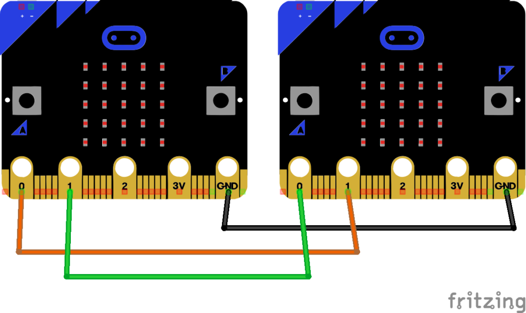
To allow two Micro:bits to communicate over a serial connection, we must make use of the ‘uart’ library. For a serial connection, two wires are needed, rx is used to receive and tx is used to transmit. When communicating between two devices, rx must attach to tx on the other device, and vice versa. It is also good practice to connect the gnd pins to ensure a common potential difference.
If we use pins 0 and 1 for our communication. we can connect two Micro:bits with a common ground, and wire each pin 0 to pin 1 on the other device.
Set one Micro:bit and the sender with the following code:
from microbit import *

# Micro:bit serial to serial - sender

# Initalise the UART
uart.init(baudrate=9600, tx=pin0, rx=pin1)

while True:
    if(button_a.is_pressed()):
        uart.write("A")
        sleep(1000)
    if(button_b.is_pressed()):
        uart.write("B")
        sleep(1000)
Use below on the receiver:
from microbit import *

# Micro:bit serial to serial - sender

# Initalise the UART
uart.init(baudrate=9600, tx=pin0, rx=pin1)

while True:
    msg = uart.readline()
    if(msg is not None):
        display.scroll(msg)
When a button is pressed on the sender, a message is sent over the serial line to the receiver which displays it on the LED matrix. While the message is short, e.g. “A”, this could be something larger. A more advanced system could parse messages to pull out commands or data.
Arduino to Micro:bit communications
While the Micro:bit is a very versitile device, the low amount of memory, available IO pins or readily available hardware libraries, can cause it to struggle. One option is to use an arduino to drive a single piece of hardware and pass messages back to the Micro:bit using the serial line. An example is an RFID reader.
There are two options for serial communications to an arduino, hardware serial or software serial. On most types of arduino, pin D0 doubles as serial rx and D1 as serial tx. In our receiver code above on the Micro:bit, we have our pin0 configured as tx and pin1 as rx. Connecting the ground of an arduino to the ground on the Micro:bit, then arduino D0 and D1 through to Micro:bit pin0 and pin1.
The following sketch on the aduino will say ‘Hi’ then increase numbers (a sketch is arduino for a program). Though, due to line ending differences it will print ‘??’ on the scrolling display of the receiver. We will deal with that in the more advanced example below.
void setup()
{
  // Open serial communications and wait for port to open:
  Serial.begin(9600);
  while (!Serial) {
    ; // wait for serial port to connect. Needed for Native USB only
  }
  Serial.println("Hi");
  delay(2000);
}

void loop() // run over and over
{
  int i=0;
  char msg[5];
  while (true) {
      sprintf(msg, "%d", i);
      Serial.println(msg);
      delay(5000);
      i++;
  }
}
There is another problem. As we now have hardware connected to the serial line, we will have problems programming our arduino. We have to remove the connections to D0 and D1 each time we want to flash a new sketch. Another option is to use the software serial library and use other pins.
Connect the aruino to the Micro:bit, mapping D2 to pin0 and D3 to pin1 as shown.
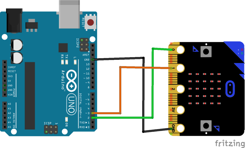
The following code now makes use of the arduino software serial library and writes over pins D2 and D3. The code on the Micro:bit does not need to change.
/* Based on example at https://www.arduino.cc/en/Tutorial/LibraryExamples/SoftwareSerialExample */
#include <SoftwareSerial.h>

SoftwareSerial mySerial(2, 3); // RX, TX

void setup()
{
  // Open serial communications and wait for port to open:
  Serial.begin(9600);
  while (!Serial) {
    ; // wait for serial port to connect. Needed for Native USB only
  }
  Serial.println("Hi");

  // set the data rate for the SoftwareSerial port
  mySerial.begin(9600);
  mySerial.println("Lo");
}

void loop() // run over and over
{
  int i=0;
  char msg[5];
  while (true) {
      sprintf(msg, "%d", i);
      mySerial.println(msg);
      Serial.println(msg);
      delay(5000);
      i++;
  }
}
You could create more ‘mySerial’ objects to communicate to multiple Micro:bits or connect one to the serial. Using the software serial is useful while you are still doing code development on the arduino. You could then switch to hardware serial later.
Arduino serial to Micro:bit – advanced
Now lets look at doing something more useful. The Micro:bit LED display is not the best thing to read longer messages with, so lets connect a small OLED display. We need the arduino doing something useful. This example adds an Adafruit PN532 RFID/NFC shield to the arduino and sends the serial number of cards and tags swiped over software serial to a Micro:bit.
Arduino code:
/* rfid_to_serial - Dave Hartburn December 2020
 *  Dumps the UID of a card to the serial console. Designed to be the RDIF workhorse for
 *  another microcontroller, such as a micro:bit.
 *
 *  Using Arduino UNO and Adafruit PN532 RFID/NFC Shield
 *  Based on the readMifare Demo program
 */

#include <Wire.h>
#include <SPI.h>
#include <Adafruit_PN532.h>
#include <SoftwareSerial.h>   // Use the software serial library

SoftwareSerial mySerial(2, 3);  // RX, TX

#define PN532_IRQ   (2)
#define PN532_RESET (3)  // Not connected by default on the NFC Shield
// Define the board
Adafruit_PN532 nfc(PN532_IRQ, PN532_RESET);

void setup() {
  Serial.begin(9600);
  mySerial.begin(9600);

  // Init RFID board
  nfc.begin();

  uint32_t versiondata = nfc.getFirmwareVersion();
  if (! versiondata) {
    Serial.print("Didn't find PN53x board");
    while (1); // halt
  }
  // Got ok data, print it out!
  Serial.print("Found chip PN5"); Serial.println((versiondata>>24) & 0xFF, HEX);
  Serial.print("Firmware ver. "); Serial.print((versiondata>>16) & 0xFF, DEC);
  Serial.print('.'); Serial.println((versiondata>>8) & 0xFF, DEC);

  // configure board to read RFID tags
  nfc.SAMConfig();

  //Serial.println("Waiting for an ISO14443A Card ...");
}

void loop() {
  uint8_t success;
  uint8_t uid[] = { 0, 0, 0, 0, 0, 0, 0 };  // Buffer to store the returned UID
  uint8_t uidLength;                        // Length of the UID (4 or 7 bytes depending on ISO14443A card type)
  int i,len;
  unsigned long uidl;
  char msg[50];

  // Wait for an ISO14443A type cards (Mifare, etc.).  When one is found
  // 'uid' will be populated with the UID, and uidLength will indicate
  // if the uid is 4 bytes (Mifare Classic) or 7 bytes (Mifare Ultralight)
  success = nfc.readPassiveTargetID(PN532_MIFARE_ISO14443A, uid, &uidLength);

  if (success) {
    // Display some basic information about the card
    //Serial.println("Found an ISO14443A card");
    //Serial.print("  UID Value: ");
    //nfc.PrintHex(uid, uidLength);

    // Convert array into single UID integer
    uidl=uid[0];
    for(i=1;i<uidLength;i++) {
      uidl = (uidl << 8) | uid[i];
    }
    //mySerial.print("CARD");
    sprintf(msg,"c=%lX",uidl);
    mySerial.print(msg);
    Serial.println(msg);

    // Wait 3 seconds
    delay(3000);
  }
}
Micro:bit code:
# Micro:bit card reader with arduino acting as
# RFID/NFC slave

from microbit import *
from ssd1306 import initialize, clear_oled
from ssd1306_text import add_text

# Init a SDD1306 screen
initialize()
clear_oled()

# Initalise the UART
uart.init(baudrate=9600, tx=pin0, rx=pin1)

while True:
    msg = uart.readline()
    if(msg is not None):
        clear_oled()
        add_text(0, 0, str(msg))
While this only reads the card serial number and displays it, you could do something more advanced such as a tick for known good cards and a cross for unknown cards.