About Buttons
Microcontrollers such as the Micro:bit all do one similar thing, accept an input (some sort of ‘message’ from the outside world), process (run some code) and output (show something to the outside world). The most common type of input everyone uses is a button.
What is a button? Essentially a button is a couple of bits of wire or metal plate that touch together when pressed. This allows electricity to flow between the connectors at either side, making the connection. There are a few different types of button each with different properties. Some stay on or stay off after being pressed (or toggled), like a light switch. Some only make a contact when the button or lever is being moved and some you push to break the circuit. The types we are looking at in this tutorial are momentary push buttons, which only make a connection while they are being pressed. The standard circuit symbols below shows a little about how they work.

There is a connection at either side, when the buttons are pressed, the two connections are joined and electricity flows.
Micro:bit Onboard Buttons
The easiest two buttons to use are the two build onto the Micro:bit board itself, labelled A and B. There is a lot of information on the Micropython tutorial page about using these. When using the microbit library, two objects are defined, button_a and button_b. You can check if these are pressed with the is_pressed() function. The following code loops checking for a button press then points an arrow to the last pressed button:
from microbit import *

while True:
    if ( button_a.is_pressed() ) :
        display.show(Image.ARROW_W)
    if ( button_b.is_pressed() ) :
        display.show(Image.ARROW_E)
While quick and easy to use, this does not help us add other buttons. By wiring in a button, it will not automatically create a button object. External buttons are connected to pins, but consider the Micro:bit pinout diagram. When you look at this, the buttons A and B are connected to pins 5 and 11. For us, this means two things. First is that when connecting hardware, if we want to use buttons A and B, we should not use pins 5 and 11 for anything else. But it also means we can read the buttons as if they were digital pins. When we read digital pins, the result can be a 1 or a 0. The following will show on the display the value of the A pin, pin 5:
from microbit import *

while True:
    display.show( pin5.read_digital() )
Try it. What does the value change to when you press the button? We often think of 1 as being on and 0 as being off, but find this works the other way round. There is a reason for this which will be revealed below. For now, as long as we are happy that 0 means a button is being pressed, if we want to rewrite the first program to use pin numbers, we can write it as:
from microbit import *

while True:
    if ( pin5.read_digital() == 0 ) :
        display.show(Image.ARROW_W)
    if ( pin11.read_digital() == 0 ) :
        display.show(Image.ARROW_E)
External Buttons
We can add external buttons to the Micro:bit to give a larger number of buttons, or to use different types of buttons. One end can connect to a data pin, but what do we connect the other end to? Consider the circuit diagram below:
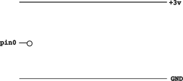
pin0 is said to be ‘floating’. It is neither connected to ground (0v) or the positive 3v. If we read the value of this, it could be anything. Putting an open button on it would leave it in the same state. Imagine a kite free to fly in the wind. If we pin it to the ground, then we know it is on the ground. If it were possible to pin it into the air, again we would know where it was. Anything else, it is at the mercy of the wind and can keep flying and crashing all day long.
Electronic inputs are the same. Unless we decide to ‘pin’ them to something, we can not predict what state they would be in. In practice, I have found an unconnected Mirco:bit input always seems to be zero. The same is not true of other micro controllers, such as a Raspberry Pi or an Arduino, so it is good practice to make sure you know what state your inputs are in. This is done with the use of pull-up or pull-down resistors.
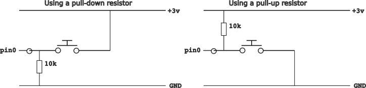
In the diagram on the left, we are using a pull-down resistor. (10k ohm is a common value for this.) When the button is not pressed, the resistor connects pin0 to ground, meaning a read_digital function will always return 0. However when the button is pressed, it connects pin0 to +3v, which the Micro:bit reads as 1. The resistor limits how much of the current can flow between +3v and GND, leaving a higher current to be detected on pin0.
In the diagram on the right, we do the opposite. pin0 is pulled high (read as 1), unless the button is pressed, at which point it is pulled low (read as 0). This means in our code, we detect a button press as a 0 and no button press as a 1.
The Micro:bit has a built in pull-up and pull-down resistors that you can turn on in the code, using the command set_pull. If you want to use your own external resistors with buttons, then you must disable these:
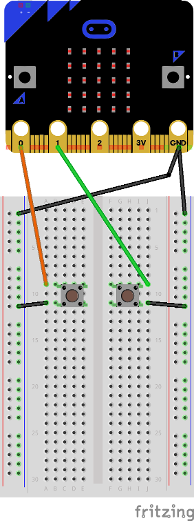
pin0.set_pull(pin0.NO_PULL)However, as they are there it is best to make use of them. If you remember, reading the internal buttons give a 1 when not pressed and a 0 when pressed, meaning they must be using the internal pull-up resistor. If we use external buttons on pins 0 and 1, we can use the same code again.
from microbit import *

# Set the pull up state for the internal resistors
pin0.set_pull(pin0.PULL_UP)
pin1.set_pull(pin1.PULL_UP)

while True:
    if ( pin0.read_digital() == 0 ) :
        display.show(Image.ARROW_W)
    if ( pin1.read_digital() == 0 ) :
        display.show(Image.ARROW_E)
Button Modules
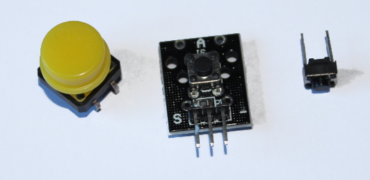
You can also use button modules such as the one in the middle of the picture above. Going from left to right, pin S connects to one of the IO pins of the Micro:bit, the middle to 3v and the right pin to GND. If you look closely, you can see a small black rectangle labelled 103 connecting S and 3v. This is a small pull-up resistor. As this has its own resistor, we need to make sure we disable the internal resistor. We can then check the button state after connecting it to pin2.
from microbit import *

# Disable the internal pull up
pin2.set_pull(pin2.NO_PULL)

while True:
    display.show ( pin2.read_digital() )
Button modules may come on their own or be included as part of a joystick module, game controller package, etc. If the instructions do not say if a pull-up or pull-down resistor is used, you should be able to check with the the above code.