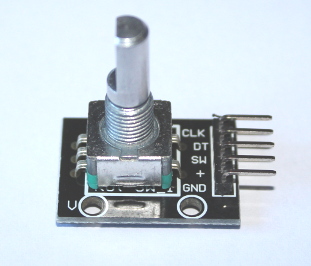
A rotary encoder, such as the common KY-040 above, is a knob that you can turn continuously either clockwise or anti-clockwise and detect which direction it is being turned. Types such as the KY-040 are known as incremental encoders. These will tell you the direction they are being turned, but can not report which direction they are pointing. The shaft can be pushed down to act like a push button. A common application for this is to navigate menu screens on devices such as 3d printers.
To connect a KY-040 to a Micro:bit, + and GND go to 3V and GND on the Micro:bit. The other three pins go to any digital input pins. In the following examples, SW goes to pin0, DT to pin1 and CLK to pin2.
For a detailed explanation of how rotary encoders work, see wikipedia. To use one, all you need to know is if CLK changes, then the encoder is being turned. If CLK is the same as DT (could be high or low), then it is being turned anti-clockwise. If CLK is different to DT it is being turned clockwise. Generally the sensitivity is changed with a sleep statement. The button on the top acts as a simple push button. The CLK and DT pins have their own internal resistors so we must disable the internal pull-up resistor to work. For a description about this, see Micro:bit Buttons. The one on the switch is still required.
This gives us a basic procedure to follow to read input from a rotary encoder:
- Define the pins in use
- Disable the internal pull-up resistors.
- Read CLK and store this in a variable for the last known state of CLK.
- Start a loop:
- Read all three input pins
- If CLK has changed since the last known state of CLK (lastCLK), the encoder is moving.
- If CLK is not equal to DT it is moving clockwise
- Otherwise it is moving anti-clockwise.
- Wait, according to the sensitivity you want
- Set lastCLK equal to CLK
- Check for button press
- Return to start of loop
In code form, this makes:
# Rotary encoder test
from microbit import *

RSW = pin0
RDT = pin1
RCLK = pin2

# KY-040 has its own pull up resistors.
# Disable the Micro:bit internal ones but
# ensure we use the one for the switch pin
RCLK.set_pull( RCLK.NO_PULL )
RDT.set_pull ( RDT.NO_PULL )
RSW.set_pull ( RSW.PULL_UP )

clkLast = RCLK.read_digital()

print ( "Ready to start" )
display.show ( Image.HAPPY )

while True:
    clk = RCLK.read_digital()
    dt = RDT.read_digital()
    sw = RSW.read_digital()

    if ( clk != clkLast ) :
        if ( clk != dt ) :
            print ( "Clockwise" )
            display.show(Image.ARROW_E)
            sleep(300)
        else:
            print ( "Anti-clockwise" )
            display.show(Image.ARROW_W)
            sleep(300)

        clkLast = clk
    else:
        # Has the switch been pressed?
        if (sw == 0) :
            display.show('X')
            sleep(500)
        else :
            display.clear()
There is a problem with this approach. If you try it and watch either the arrows or serial lines, you find while turning the encoder, you occasionally get the wrong direction reported. This is known as ‘switch bounce’ and is often caused by cheaper components in encoders such as the KY-040. There are many ways to look at solving this, either in hardware using capacitors or in code. In a few tests with capacitors, I did not find a significant difference. However I always found that the wrong direction was reported once in a row, never twice.
A ‘quick and dirty’ solution is to wrap up the detection into a function which takes a number of readings then reports back which direction was detected the most. This does mean it will take a little longer to react to a turn or change in direction, but only by a fraction of a second. In the code below, the function readEncoder returns a pair of values for the direction and the state of the switch. A 0 represents no movement, 1 for clockwise movement and -1 for anti-clockwise.
In python, you can build lists of values in brackets with a comma, e.g. a=(2, 4, 8). To access the first element of the list, use square brackets, a[0]. For the third value, a[2]. This allows us to return the direction as the first value and the switch state as the second. The function in the below code takes a few attempts to read the encoder direction and returns a pair of values, the first for the direction and the second for the switch state.
# Rotary encoder test
from microbit import *

RSW = pin0
RDT = pin1
RCLK = pin2

# KY-040 has its own pull up resistors.
# Disable the Micro:bit internal ones but
# ensure we use the one for the switch pin
RCLK.set_pull(RCLK.NO_PULL)
RDT.set_pull(RDT.NO_PULL)
RSW.set_pull(RSW.PULL_UP)

def readEncoder():
    # Return a pair of values direction and switch state
    #   0 = no movement
    #   1 = clockwise
    #   2 = anti-clockwise

    # Set sensitivity - how long we wait between readings in ms
    sens = 50
    # Accuracy is how many checks we perform. This should at least
    # be 3. Note that the more checks, the longer it will take and
    # the greater the chance of the direction changing while we checks
    acc = 5

    # Record the last known state of the CLK line
    clkLast = RCLK.read_digital()

    # Set direction counters, clockwise and anti-clockwise
    cw = 0
    ac = 0

    # Checking loop
    for i in range(0, acc):
        # Read data from the encoder
        clk = RCLK.read_digital()
        dt = RDT.read_digital()
        sw = RSW.read_digital()

        if(clk != clkLast):
            # print ("clkLast = "+str(clkLast)+" - clk = "+str(clk)+" - dt = "+str(dt))
            if(clkLast != dt):
                # Clockwise, add 1 to clockwise count
                cw = cw+1
            else:
                # Anti-clockwise, add 1 to anti-clockwise count
                ac = ac+1

            # Record the last known state of the clock
            clkLast = clk
            # Wait according to sensitivity setting
            sleep(sens)

    # Initially assume the direction is 0
    d = 0
    # Check the clockwise and anti-clockwise counters
    # If they are the same, no change to d is made. We assume
    # the encoder is not moving
    if(cw > ac):
        # More clockwise movement than anti-clockwise
        d = 1
    elif(ac > cw):
        # More anti-clockwise movement than clockwise
        d = -1

    # Return data as a pair
    # We can return the value of the switch directly
    return (d, sw)
# End of readEncoder

print("Ready to start")
display.show(Image.HAPPY)
sleep(1000)

# Main loop
while True:
    r = readEncoder()

    # Check the direction and report. The screen
    # will show the last recorded direction
    if(r[0] == 1):
        # Clockwise movement
        print("Clockwise")
        display.show(Image.ARROW_E)
    elif(r[0] == -1):
        # Anti-clockwise movement
        print("Anti-clockwise")
        display.show(Image.ARROW_W)

    # Check for a switch press
    if(r[1] == 0):
        display.show('X')
        sleep(500)
        display.clear()